606.2 Guard Cable
606.2.1 Guard Cable Types
Guard cable consists of twisted wire ropes mounted on weak posts. There are two types of guard cable systems in use on Missouri roadways: low-tension and high-tension. All new installations will be high-tension.
606.2.1.1 Low-Tension. Existing low-tension guard cable may remain in place as long as the guard cable system is in serviceable condition. Low-tension guard cable shall not be used for new barrier installations. Existing low-tension guard cable systems may be repaired when damaged (see EPG 606.2.4 Maintenance and Repair) if practical. When low-tension guard cable is reaching the end of its serviceable condition, the District may consider letting a contract to replace the low-tension guard cable with high-tension guard cable (or other approved barrier).

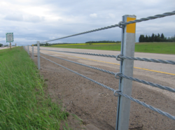
606.2.1.2 High-Tension. High-tension guard cable consists of three or four pre-stressed cables supported by weak posts. All high-tension guard cable shall meet NCHRP 350 or MASH 2016 TL-3 requirements and be on MoDOT’s approved products list End Terminals, Crash Cushions and Barrier Systems. All high-tension guard cable shall be installed per manufacturer’s requirements.
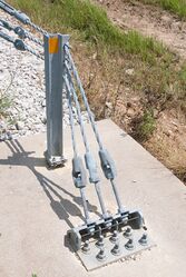
A common installation of high-tension guard cable employs concrete footings into which metal tubes are cast, forming sockets. The socket allows a post to be replaced with relative ease during a repair operation. The damaged post can be removed from the socket and replaced with a new post. Socketed systems eliminate the requirement for specialized post driving equipment and subsurface utility location for each repair.
- Summary, 2006
- Report, 2010
- See also: Research Publications
606.2.2 Warrants
Analyses of cross-median incident history and traffic volume provide valuable information in determining the likelihood of future incidents on these routes. In order to prevent future incidents, it is important to focus safety efforts on locations that will benefit the most from safety countermeasures.
The risk of cross-median crashes can be influenced by median width and the traffic volume on both roadways (two-way AADT). Figure 606.2.2 shows various levels for implementation based on the anticipated benefits of reducing crashes compared to costs for installation, maintenance, and overall crash impact. The Highway Safety and Traffic Division may be contacted for additional details on how the anticipated benefits of guard cable installation were determined.

|
| Figure 606.2.2, Median Guard Cable Levels as Related to Median Width and Two-Way AADT |
Median guard cable should be installed in Level 1 locations.
Median guard cable may be installed in Level 2 or 3 locations based on engineering judgment. Guard cable may be installed on Level 4, but is not typical and should have additional justification based on the context of the location.
606.2.2.1 Data. Analysis of incidents on a candidate corridor should focus on cross-median incidents on that route.
It is important this data analysis is accurate and complete for all roadways. Due to at-grade intersection incidents on these routes, a simple query of cross-median incidents may include unwanted events and exclude necessary ones. Accuracy of this data is vital in decision-making.
The data should be reviewed regularly to validate priorities and identify any emerging cross-median safety concerns. A regular review of divided highway traffic volume and incidents will provide information to address cross-median incidents.
606.2.2.2 Traffic Volume. Recent research has connected traffic volume growth directly to cross-median incidents. As volume increases, the probability of a motorist crossing the median and hitting an oncoming vehicle also increases. Instead of relying solely on incident history, there is an opportunity to proactively address this incident type before the incidents occur by studying traffic volume patterns and installing a system of median guard cable on routes with sharply increasing volumes. See Figure 606.2.2 for the anticipated impact traffic volume has on crash risk and anticipated value for guard cable installation.
606.2.2.3 Median Width. Recent national experience has shown that cross-median incidents can occur on highways with median widths above MoDOT's initial 60 ft. threshold. Although this width has largely proven to be effective in deterring such incidents, no route will be excluded from analysis solely on the basis of median width. Divided highways with very wide medians are expected to have a low risk of cross-median incidents. See Figure 606.2.2 for the anticipated impact median width has on crash risk and anticipated value for guard cable installation.
606.2.3 Design and Installation Guidelines
606.2.3.1 Lateral Placement in the Median
Dynamics of Cross-Median Incidents. When a vehicle leaves the roadway and enters the median, certain predictable dynamics occur. Vehicles may enter the median at a variety of speeds and angles but for the purposes of roadside safety research and testing, a 62 mph departure at a 25° angle is generally used.
Upon departure, a vehicle will initially continue along its vertical trajectory. As the inslope falls away along the 25° vehicle path, the vehicle effectively becomes briefly airborne. When the vehicle's inertia can no longer overcome gravity, it lands and its suspension is deeply compressed. As the vehicle continues to travel through the median, the suspension rebounds and the bumper of the vehicle stays at a relatively constant height throughout the remainder of the errant journey.
Every guard cable incident is slightly different because of a host of site-specific factors. In general, however, the front of the vehicle must engage at least two of the three or four cables present in order to be contained by the system. Given the dynamics described above, lateral placement of the cable can be grouped into two main categories: medians wider than 30 ft. and those narrower than 30 ft.

Medians 30 ft. or wider. The guard cable should be installed no more than 4 ft. downslope of the edge of the shoulder. With wider shoulders, the downslope location could be less than 4 ft., but in any case, there shall be a minimum of 8 ft. between the barrier and the edge of traveled way. There are several advantages to this location but chief among them is the performance of the system in a incident. At the 4 ft. downslope location, the errant vehicle adjacent to the barrier, while airborne, is not at a great enough altitude to override the cable during a front side encounter. From the opposing direction, or backside, the suspension of the errant vehicle will have recovered enough to allow an impact to occur under relatively normal impact conditions.
If the 8 ft. separation cannot be obtained, the designer must work with the Central Office Design Division to assess the potential safety impacts of a decreased deflection distance. A different barrier system should be considered.
Medians narrower than 30 ft. In medians narrower than 30 ft., the guard cable should be installed within 1 ft. of the vertex of either a V or flat-bottomed ditch. As previously discussed, this location performs the most advantageously. When placed 4 ft. downslope in narrow medians, the suspension of the vehicle impacting from the back side (i.e. the opposite direction) is most tightly compressed near that location. A compressed suspension has potential to underride the system.
Alternating Sides. The designer may choose to alternate the sides of the median where the barrier is placed for the purpose of reducing any shy line issues or discomfort for motorists. The change should occur at natural breaks in the barrier such as emergency crossovers or median bridge columns.
606.2.3.2 Parallel Installations
In-service experience with parallel installations has shown less than desirable results. The close proximity of each installation to traffic has caused an inordinately high incidence of nuisance hits resulting in higher than acceptable long-term maintenance costs. Vegetative maintenance is also a concern.
Parallel installations of guard cable should not be used. Instead, designers should rely upon guard cable designed for the situation as a single run or consider a barrier system other than guard cable.
606.2.3.3 Post Spacing
-
 Anchor Assembly
 -
 Vegetation Barrier


While guard cable has been tested and approved with post spacing ranging from 6.5 to 32.5 ft., it is widely believed that the wider post spacing leads to greater deflections and an increased likelihood of vehicle penetration due to underride or traveling between the cables. For this reason, post spacing should not exceed the conventional limit of 20 ft or the manufacturer's recommendation. Additionally, increasing post spacing through horizontal curves increases the opportunity for the cable to assume a chord length if the posts are damaged. If enough posts are damaged, the cable could project into the travelway on the inside of the curve.
606.2.3.4 Slopes
Proprietary high-tension systems are approved for use on slopes with gradients between 1V:6H (6:1) to 1V:4H (4:1).
606.2.3.5 Vegetative Barrier
Vegetation control in the area between the cable and the passing lane should be addressed. Failure to provide some positive form of vegetation control will hinder the future maintenance of the system. The core team shall consult with the local maintenance personnel to arrive at a vegetative control measure that is mutually agreeable. Vegetation control may not be omitted from a project as a practical design or value engineering measure. Control of vegetation around guard cable systems can be largely addressed with the addition of a vegetative barrier. The use of a vegetative barrier reduces future hand mowing or herbicide operations. See JSP2404 Vegetative Barrier Pavement for design and construction requirements. See EPG 606.2.4 Maintenance and Repair for vegetation maintenance.
606.2.3.6 Termination at Crossovers and Emergency Crossovers
The design for guard cable termination as well as the grading for the crossover shall be in accordance with Standard Plan 606.42. Refer to EPG 240.4 Guard Cable Termination at Emergency Crossovers for additional information.
606.2.4 Maintenance and Repair
Guard cable is only as functional as its ongoing maintenance and repair. Proper maintenance and incident repair will ensure that the system is always in a state of functionality to provide motorists a greater level of safety on Missouri roadways.
Vegetation Maintenance. District maintenance shall provide vegetative control around guard cable systems. Vegetation maintenance measures should include mowing, herbicides, a geotextile-aggregate strip or an asphalt apron may have been constructed during initial installation.
Cable Tension. If pre-stressed cables are used for high-tension systems and compensators are properly compressed for low-tension systems, the tension in the cable should properly acclimate to any weather condition. Tension logs shall be stored in the contract specific eProjects folder. The tension log form is available at EPG 101 Standard Forms.
Cable Height. The importance of cable height to properly capture and redirect errant vehicles has been demonstrated. Although cable height is relatively static in all systems, erosion and tire rutting under the barrier can sometimes cause a localized increase in height, resulting in possible underride. When ditch erosion or rutting causes the cable heights to be outside the manufacturer’s recommended maximum, corrective measures should be performed by either the on-call contractor or by in-house Maintenance forces.
Maintenance personnel should be aware of minimum and maximum cable heights and encouraged to identify locations where erosion or the accumulation of silt have altered the relative cable height.
Median Condition. The median condition with respect to rutting, loss of vegetation and incident debris should be remedied by Maintenance forces following each incident.
Guard Cable Repair. Incident repairs shall be performed by the on-call contractor. See EPG 147.3.10 Guardrail and Guard Cable Repair for additional Job Order Contracting requirements for guard cable repairs.
Splices. Cable repair splices for low-tension systems will be no closer than 400 feet per cable within a 2000-foot run (anchor to anchor). When a repair to a low-tension cable would require splices closer than 400 feet, repair with a sufficient length of cable necessary to ensure splices are separated by no less than 400’.
Cable repair splices for high-tension systems will be no closer than 200 feet per cable within a 1000-foot run (turn buckle to turn buckle). When a repair to a high-tension cable would require splices closer than 200 feet, repair with a sufficient length of cable necessary to ensure splices are separated by no less than 200’.
606.2.5 Maintenance Planning Guidelines for Guard Cable
See Maintenance Planning Guideline for Guard Cable.
Index of all Maintenance Planning Guidelines.
606.2.6 Construction Inspection Guidelines for Guard Cable
For Sec 606.50.2. The embankment slope between the shoulder and the guard cable should be 1V:6H (6:1) or flatter, unless the system is approved for use on slopes as steep as 1V:4H (4:1). If only one run of high-tension guard cable is installed in the median, the slope on both sides of the guard cable should be 1V:6H (6:1) or flatter, unless the system is approved for use on slopes as steep as 1V:4H (4:1). No exceptions should be allowed unless approved by the Central Office. This is essential for the guard cable to perform as designed.
The embankment slope behind the guard cable is not critical (may be as steep as 1V:2H (2:1)) if another run of high-tension guard cable is installed on the other side of the median to prevent crossovers from that direction of traffic or if adequate clear zone is provided in the other direction of traffic. Such "double runs" are discouraged, however, since both the initial and lifetime costs are doubled.
| Sieve Size | Percent Passing by Weight (mass) |
|---|---|
| 3 in. (75mm) | 100 |
| 1 in. (25mm) | 80 |
| No. 4 (4.75mm) | 0-35 |
Aggregate Bedding (for Sec. 606.50.2.4). Predominantly one-sized stone as a bedding material for guard cable, as currently specified in Sec 606.50.4, will act as marbles when a vehicle impacts the bedding material and will likely result in an impacting vehicle to dive under the cable system and continue across the median into the opposing traffic, thereby defeating the purpose of the guard cable system. This is elevated to even a larger safety issue where contractors have provided sand or gravel as the bedding material, which have a greater tendency to roll like marbles when impacted and increases the probability for a vehicle to dive beneath the barrier system. In the interim of getting a specification revision, existing jobs should be change ordered to a bedding material consisting of a uniform, angular graded material of a gradation similar to that shown below. Verification of the gradation should be accomplished by visual inspection, and when in suspect, a sieve analysis should be conducted.
Delineators (for Sec. 606.50.2.5). All high-tension guard cable, regardless of the location of the guard cable, should be delineated, with delineator spacing, reflective sheeting and reflector colors in accordance with Sec 606.10.2.3.