620.2 Pavement and Curb Markings (MUTCD Chapter 3B): Difference between revisions
m removed metric values, per TR |
Per Traffic, revision to bring policy into substantial compliance with the 2009 MUTCD. |
||
| Line 5: | Line 5: | ||
'''Option.''' Centerline pavement markings may be placed at a location that is not the geometric center of the roadway. | '''Option.''' Centerline pavement markings may be placed at a location that is not the geometric center of the roadway. | ||
'''Standard.''' The centerline markings on two-lane, two-way roadways shall be one of the following as shown in [[# | '''Standard.''' The centerline markings on two-lane, two-way roadways shall be one of the following as shown in [[#Fig. 620.2.2.0.1|Fig. 620.2.2.0.1, Examples of Two-Lane, Two-Way Marking Applications]]: | ||
:A. Two-direction passing zone markings consisting of a normal broken yellow line where crossing the centerline markings for passing with care is permitted for traffic traveling in either direction; | :A. Two-direction passing zone markings consisting of a normal broken yellow line where crossing the centerline markings for passing with care is permitted for traffic traveling in either direction; | ||
:B. One-direction no-passing zone markings consisting of a normal broken yellow line and a normal solid yellow line where crossing the centerline markings for passing with care is permitted for the traffic traveling adjacent to the broken line, but is prohibited for traffic traveling adjacent to the solid line; | :B. One-direction no-passing zone markings consisting of a double yellow yellow line, one of which is a normal broken yellow line and the other is a normal solid yellow line where crossing the centerline markings for passing with care is permitted for the traffic traveling adjacent to the broken line, but is prohibited for traffic traveling adjacent to the solid line; or | ||
:C. Two-direction no-passing zone markings consisting of two normal solid yellow lines where crossing the centerline markings for passing is prohibited for traffic traveling in either direction. | :C. Two-direction no-passing zone markings consisting of two normal solid yellow lines where crossing the centerline markings for passing is prohibited for traffic traveling in either direction. | ||
The centerline markings on undivided two-way roadways with four or more lanes for moving motor vehicle traffic always available shall be the two-direction no-passing zone markings consisting of | A single solid yellow line shall not be used as a centerline marking on a two-lane roadway. | ||
The centerline markings on undivided two-way roadways with four or more lanes for moving motor vehicle traffic always available shall be the two-direction no-passing zone markings consisting of a solid double yellow line separated by 4 in. as shown in [[#Fig. 620.2.2.0.2|Fig. 620.2.2.0.2, Examples of Four-Lane Undivided, Two-Way Marking Applications]]. | |||
See [[620.1 General (MUTCD Chapter 3A)#620.1.5 Widths and Patterns of Longitudinal Pavement Markings (MUTCD Section 3A.05)|Widths and Patterns of Longitudinal Pavement Markings]] for line patterns. | See [[620.1 General (MUTCD Chapter 3A)#620.1.5 Widths and Patterns of Longitudinal Pavement Markings (MUTCD Section 3A.05)|Widths and Patterns of Longitudinal Pavement Markings]] for line patterns. | ||
| Line 24: | Line 26: | ||
'''Guidance.''' After the centerline is obliterated from the entire route, or a significant portion of the route, it should be replaced using the 2 line systems. | '''Guidance.''' After the centerline is obliterated from the entire route, or a significant portion of the route, it should be replaced using the 2 line systems. | ||
On two-way roadways with three through lanes for moving motor vehicle traffic, two lanes should be designated for traffic in one direction by using one- or two-direction no-passing zone markings as shown in [[# | On two-way roadways with three through lanes for moving motor vehicle traffic, two lanes should be designated for traffic in one direction by using one- or two-direction no-passing zone markings as shown in [[#Fig. 620.2.2.0.4|Fig. 620.2.2.0.4, Examples of Three-Lane, Two-Way Marking Applications]]. | ||
'''Standard.''' Centerline markings shall be placed on all paved roads that traveled ways 18 ft. or wider. Centerline markings shall also be placed on all paved two-way streets or highways that have three or more lanes for moving motor vehicle traffic. | '''Standard.''' Centerline markings shall be placed on all paved roads that have traveled ways 18 ft. or wider. Centerline markings shall also be placed on all paved two-way streets or highways that have three or more lanes for moving motor vehicle traffic. | ||
'''Guidance.''' Engineering judgment should be used in determining whether to place centerline markings on traveled ways that are narrower than 18 ft. because of the potential for traffic encroaching on the pavement edges, traffic being affected by parked vehicles, and traffic encroaching into the opposing traffic lane. Engineering judgment should also be used to determine if the pavement can support centerline markings. | '''Guidance.''' Engineering judgment should be used in determining whether to place centerline markings on traveled ways that are narrower than 18 ft. because of the potential for traffic encroaching on the pavement edges, traffic being affected by parked vehicles, and traffic encroaching into the opposing traffic lane. Engineering judgment should also be used to determine if the pavement can support centerline markings. | ||
'''Standard.''' Diversion bubbles shall be marked using 2 solid yellow lines to form both sides of the bubble at the beginning of a left turn bay where the bubble separates travel in opposite directions, and each installation of these markings will require individual treatment; therefore, no set dimensions have been established for their placement. Additional markings, such as cross-hatching inside the bubble, if used, shall also be yellow in color (See [[# | '''Standard.''' Diversion bubbles shall be marked using 2 solid yellow lines to form both sides of the bubble at the beginning of a left turn bay where the bubble separates travel in opposite directions, and each installation of these markings will require individual treatment; therefore, no set dimensions have been established for their placement. Additional markings, such as cross-hatching inside the bubble, if used, shall also be yellow in color (See [[#Fig. 620.2.2.0.3|Fig. 620.2.2.0.3, Marking for Median Islands for Left Turn Bays]]). | ||
'''Guidance.''' The taper length of transition zones should not be less than taper length calculated using the equations L = S x W or L = WS2/60 as defined in [[#620.2.9 Lane Reduction Transition Markings (MUTCD Section 3B.09)|Lane Reduction Transition Markings]]. Installation of these markings should conform to the established general patterns. | '''Guidance.''' The taper length of transition zones should not be less than taper length calculated using the equations L = S x W or L = WS2/60 as defined in [[#620.2.9 Lane Reduction Transition Markings (MUTCD Section 3B.09)|Lane Reduction Transition Markings]]. Installation of these markings should conform to the established general patterns. | ||
| Line 36: | Line 38: | ||
==620.2.2 No-Passing Zone Pavement Markings and Warrants (MUTCD Section 3B.02)== | ==620.2.2 No-Passing Zone Pavement Markings and Warrants (MUTCD Section 3B.02)== | ||
'''Standard.''' No-passing zones shall be marked by either the one direction no-passing zone pavement markings or the two-direction no-passing zone pavement markings described previously and shown in [[# | '''Standard.''' No-passing zones shall be marked by either the one direction no-passing zone pavement markings or the two-direction no-passing zone pavement markings described previously and shown in [[#Fig. 620.2.2.0.1|Fig. 620.2.2.0.1, Examples of Two-Lane, Two-Way Marking Applications]] and [[#Fig. 620.2.2.0.4|Fig. 620.2.2.0.4, Examples of Three-Lane, Two-Way Marking Applications]]. | ||
When centerline markings are used, no-passing zone markings shall be used on two-way roadways at lane reduction transitions (see [[#620.2.9 Lane Reduction Transition Markings (MUTCD Section 3B.09)|Lane Reduction Transition Markings (MUTCD Section 3B.09)]]) and on approaches to obstructions that must be passed on the right (see [[#620.2.10 Approach Markings for Obstructions (MUTCD Section 3B.10)|Approach Markings for Obstructions (MUTCD Section 3B.10)]]). | When centerline markings are used, no-passing zone markings shall be used on two-way roadways at lane reduction transitions (see [[#620.2.9 Lane Reduction Transition Markings (MUTCD Section 3B.09)|Lane Reduction Transition Markings (MUTCD Section 3B.09)]]) and on approaches to obstructions that must be passed on the right (see [[#620.2.10 Approach Markings for Obstructions (MUTCD Section 3B.10)|Approach Markings for Obstructions (MUTCD Section 3B.10)]]). | ||
On two-way, two- or three-lane roadways where centerline markings are installed, no-passing zones shall be established at vertical and horizontal curves and other locations where an engineering study indicates that passing must be prohibited because of inadequate sight distances or other special conditions. | |||
On roadways with centerline markings, no-passing zone markings shall be used at horizontal or vertical curves where the passing sight distance is less than the minimum necessary for reasonably safe passing at the 85th-percentile speed or the posted or statutory speed limit, whichever is higher, as shown in [[#Table 620.2.2.1 Minimum Passing Sight Distances|Table 620.2.2.1 Minimum Passing Sight Distances]]. The passing sight distance on a vertical curve is the distance at which an object 3.5 ft. (above the pavement surface can be seen from a point 3.5 ft. above the pavement (see Figure 620.2.2.2.1 Method of Locating and Determining the Limit of No-Passing Zones at Curves). Similarly, the passing sight distance on a horizontal curve is the distance measured along the centerline (or right-hand lane line of a three-lane roadway) between two points 3.5 ft. above the pavement on a line tangent to the embankment or other obstruction that cuts off the view on the inside of the curve (see Figure 620.2.2.2.1 Method of Locating and Determining the Limit of No-Passing Zones at Curves). | |||
'''Guidance.''' Where the distance between successive no-passing zones is less than 400 ft., no-passing markings should connect the zones. | '''Guidance.''' Where the distance between successive no-passing zones is less than 400 ft., no-passing markings should connect the zones. | ||
| Line 46: | Line 52: | ||
'''Standard.''' Where the no passing zone crosses a speed limit boundary, such as at city limits, the no passing zone shall be logged using the criteria for that section of roadways based on the posted speed limit or 85th percentile speed, whichever is greater only if there is a sufficient length of roadway to warrant this change. | '''Standard.''' Where the no passing zone crosses a speed limit boundary, such as at city limits, the no passing zone shall be logged using the criteria for that section of roadways based on the posted speed limit or 85th percentile speed, whichever is greater only if there is a sufficient length of roadway to warrant this change. | ||
No-passing zone markings shall be used on approaches to highway-rail grade crossings in conformance with [http://mutcd.fhwa.dot.gov/index.htm MUTCD Section 8B. | No-passing zone markings shall be used on approaches to highway-rail grade crossings in conformance with [http://mutcd.fhwa.dot.gov/index.htm MUTCD Section 8B.27]. The minimum length of a no-passing zone on a railroad crossing approach shall be 500 feet. | ||
'''Option.''' In addition to pavement markings, no-passing zone signs (see [[903.5 Regulatory Signs#903.5.25 DO NOT PASS Sign (R4-1) (MUTCD Section 2B.29)|DO NOT PASS Sign]], [[903.5 Regulatory Signs#903.5.26 PASS WITH CARE (R4-2) (MUTCD Section 2B.30)|PASS WITH CARE Sign]], and [[903.6 Warning Signs#903.6.37 NO PASSING ZONE Sign (W14-3) (MUTCD Section 2C.35)|NO PASSING ZONE Sign]]) may be used to emphasize the existence and extent of a no-passing zone. The approval of the State Traffic Engineer is required before signs are used to enhance no-passing zones. | '''Option.''' In addition to pavement markings, no-passing zone signs (see [[903.5 Regulatory Signs#903.5.25 DO NOT PASS Sign (R4-1) (MUTCD Section 2B.29)|DO NOT PASS Sign]], [[903.5 Regulatory Signs#903.5.26 PASS WITH CARE (R4-2) (MUTCD Section 2B.30)|PASS WITH CARE Sign]], and [[903.6 Warning Signs#903.6.37 NO PASSING ZONE Sign (W14-3) (MUTCD Section 2C.35)|NO PASSING ZONE Sign]]) may be used to emphasize the existence and extent of a no-passing zone. The approval of the State Traffic Engineer is required before signs are used to enhance no-passing zones. | ||
| Line 55: | Line 58: | ||
'''Support.''' Section 11-307 of the “Uniform Vehicle Code (UVC) Revised” contains further information regarding no-passing zones. The “UVC” can be obtained from the [www.ncutlo.org National Committee on Uniform Traffic Laws and Ordinances]. | '''Support.''' Section 11-307 of the “Uniform Vehicle Code (UVC) Revised” contains further information regarding no-passing zones. The “UVC” can be obtained from the [www.ncutlo.org National Committee on Uniform Traffic Laws and Ordinances]. | ||
'''Guidance.''' The | '''Guidance.''' The centerline marking on multi-lane, undivided roadways with 4 or more lanes should be marked using 2 solid yellow lines, 4 in. wide and separated by a minimum of 4 inches. | ||
<div id="Fig. 620.2.2.0.1"></div> | |||
<div id=" | [[Image:620.2.2.0.1 3B1.jpg|thumb|center|700px|<center>'''Fig. 620.2.2.0.1, Examples of Two-Lane, Two-Way Marking Applications (MUTCD Fig. 3B-1)'''</center>]] | ||
[[Image:620.2 Examples of Two-Lane, Two-Way Marking Applications (MUTCD Fig. 3B-1) | |||
<div id="Fig. 620.2.2.0.2"></div> | |||
<div id="Examples of | [[Image:620.2.2.0.2 3B2.jpg|thumb|center|700px|<center>'''Fig. 620.2.2.0.2, Examples of Four-or-more-Lane, Two-Way Marking Applications (MUTCD Fig. 3B-2)'''</center>]] | ||
[[Image:620.2 Examples of Three-Lane, Two-Way Marking Applications (MUTCD Fig. 3B-3) | |||
<div id="Fig. 620.2.2.0.3"></div> | |||
[[Image: Fig. 620.2.2.0.3.jpg|thumb|center|700px|<Center>'''Fig. 620.2.2.0.3, Marking for Median Islands for Left Turn Bays'''</center>]] | |||
<div id="Fig. 620.2.2.0.4"></div> | |||
[[Image:620.2.2.0.4 3B3.jpg|thumb|center|700px|<center>'''Fig. 620.2.2.0.4, Examples of Three-Lane, Two-Way Marking Applications (MUTCD Fig. 3B-3)'''</center>]] | |||
'''Standard.''' In no case shall a no passing zone be less than 500 ft. long. If the calculated no passing zone is less than 500 ft., an additional length of marking shall be added to the leading end of the zone to lengthen it to the full 500 feet. | '''Standard.''' In no case shall a no passing zone be less than 500 ft. long. If the calculated no passing zone is less than 500 ft., an additional length of marking shall be added to the leading end of the zone to lengthen it to the full 500 feet. | ||
On three-lane roadways where the direction of travel in the center lane transitions from one direction to the other, a no-passing buffer zone shall be provided in the center lane as shown in [[903.13 Typical Signing Applications#Figure 903.13.24 Typical Signing for Passing Lanes|Figure 903.13.24 Typical Signing for Passing Lanes]]. A lane transition shall be provided at each end of the buffer zone. | On three-lane roadways where the direction of travel in the center lane transitions from one direction to the other, a no-passing buffer zone shall be provided in the center lane as shown in [[903.13 Typical Signing Applications#Figure 903.13.24 Typical Signing for Passing Lanes|Figure 903.13.24 Typical Signing for Passing Lanes]]. A lane transition shall be provided at each end of the buffer zone. | ||
The buffer zone shall be a median island that is at least 50 ft. long. | The buffer zone shall be a flush median island formed by two sets of double yellow centerline markings that is at least 50 ft. long. | ||
'''Guidance.''' For three-lane roadways having a posted or statutory speed limit of | '''Guidance.''' For three-lane roadways having a posted or statutory speed limit of 45 mph or greater, the lane transition taper length should be computed by the formula L = WS for speeds in mph. For roadways where the posted or statutory speed limit is less than 45 mph, the formula L = WS2/60 for speeds in mph should be used to compute taper length. Under both formulas, L equals the taper length in feet, W equals the width of the center lane or offset distance in feet, and S equals the 85th-percentile speed or the posted or statutory speed limit, whichever is higher. | ||
'''Standard.''' The minimum lane transition taper length shall be 100 ft. in urban areas and 200 ft. in rural areas. | '''Standard.''' The minimum lane transition taper length shall be 100 ft. in urban areas and 200 ft. in rural areas. | ||
When used to delineate between climbing lanes on long grades, a no passing zone shall be provided on the taper as well as a distance of 1/2 the taper length in advance of and following the taper. | When used to delineate between climbing lanes on long grades, a no passing zone shall be provided on the taper as well as a distance of 1/2 the taper length in advance of and following the taper. | ||
'''Guidance.''' The tangent line should not extend beyond the right-of-way line. Consideration should be given to vegetation or any other seasonal variations when determining the locations of no passing zones (see [[# | '''Guidance.''' The tangent line should not extend beyond the right-of-way line. Consideration should be given to vegetation or any other seasonal variations when determining the locations of no passing zones (see [[#Fig. 620.2.2.2.1|Fig. 620.2.2.2.1, Method of Locating and Determining the Limit of No-Passing Zones at Curves]]). | ||
When performing a speed study, an attempt should be made to complete a minimum of 1 study per 10-mile section of roadway, each at a typical section of the roadway. This spacing may vary depending on the degree of uniformity, varying geometrics, cross sections and roadside development. Generally, the criteria determined for a route should be consistent throughout its entire length, without fluctuation due to short changes in terrain that could produce lower speeds. Substantial sections of roadway that have been reconstructed, and thereby provide an increased prevailing speed, should be considered independently of the overall route. | When performing a speed study, an attempt should be made to complete a minimum of 1 study per 10-mile section of roadway, each at a typical section of the roadway. This spacing may vary depending on the degree of uniformity, varying geometrics, cross sections and roadside development. Generally, the criteria determined for a route should be consistent throughout its entire length, without fluctuation due to short changes in terrain that could produce lower speeds. Substantial sections of roadway that have been reconstructed, and thereby provide an increased prevailing speed, should be considered independently of the overall route. | ||
'''Support.''' The beginning of a no-passing zone at point “a” in [[# | '''Support.''' The beginning of a no-passing zone at point “a” in [[#Fig. 620.2.2.2.1|Fig. 620.2.2.2.1, Method of Locating and Determining the Limit of No-Passing Zones at Curves]] is that point where the sight distance first becomes less than that specified in [[#Table 620.2.2.1|Table 620.2.2.1 Minimum Passing Sight Distances for No-Passing Zone Markings]]. The end of the no-passing zone at point “b” in Fig. 620.2.2.2.1 Method of Locating and Determining the Limit of No-Passing Zones at Curves is that point at which the sight distance again becomes greater than the minimum specified. | ||
The values of the minimum passing sight distance that are shown in Table 620.2.2.1 are for operational use in marking no-passing zones and are less than the values that are suggested for geometric design by AASHTO's ''A Policy on Geometric Design of Highways and Streets''. | |||
'''Guidance.''' The lane delineation between the climbing lanes provided on long grades, and the descending lane, should be accomplished using | '''Guidance.''' The lane delineation between the climbing lanes provided on long grades, and the descending lane, should be accomplished using centerline markings. In these cases, if the conditions are adequate, a passing zone should be provided for traffic traveling in the single, down grade, lane. A no passing zone should be provided for the length of the climbing lanes for traffic traveling up grade. The up grade climbing lanes should be delineated from each other using a white broken line (see [[#Fig. 620.2.9.2|Fig. 620.2.9.2 Standard Pavement Markings for Climbing Lanes]]). | ||
===620.2.2.1 Establishing and Recording No Passing Zones=== | ===620.2.2.1 Establishing and Recording No Passing Zones=== | ||
| Line 107: | Line 106: | ||
'''Standard.''' MoDOT has made available to the districts an electronic system that shall be used in documenting no-passing zones. | '''Standard.''' MoDOT has made available to the districts an electronic system that shall be used in documenting no-passing zones. | ||
<div id="Table 620.2.2.1"></div> | |||
<div id=" | {| border="1" class="wikitable" style="margin: 1em auto 1em auto" style="text-align:center" width=700px align="center" | ||
{| border="1" class="wikitable" style="margin: 1em auto 1em auto" style="text-align:center" | |+ '''Table 620.2.2.1 Minimum Passing Sight Distances for No-Passing Zone Markings (MUTCD Table 3B-1)''' | ||
|+ '''Minimum Passing Sight Distances (MUTCD Table 3B-1)''' | |||
! style="background:#BEBEBE"| 85th Percentile of Posted or Statutory Speed Limit (mph) !! style="background:#BEBEBE"| Minimum Passing Sight Distance (ft.) | ! style="background:#BEBEBE"| 85th Percentile of Posted or Statutory Speed Limit (mph) !! style="background:#BEBEBE"| Minimum Passing Sight Distance (ft.) | ||
|- | |- | ||
| Line 138: | Line 136: | ||
'''Standard.''' The centerline markings on bridges, having a clear roadway width of 16 ft. or greater, shall be the same as that marked on the adjoining roadway. | '''Standard.''' The centerline markings on bridges, having a clear roadway width of 16 ft. or greater, shall be the same as that marked on the adjoining roadway. | ||
Centerline markings shall not be placed on one lane bridges. When dealing with this type of bridge, the centerline markings shall stop a distance of five 500 ft. from each edge of the bridge deck. Therefore, the length of surface not receiving | Centerline markings shall not be placed on one lane bridges. When dealing with this type of bridge, the centerline markings shall stop a distance of five 500 ft. from each edge of the bridge deck. Therefore, the length of surface not receiving centerline marking shall be 1,000 ft. plus the length of the bridge deck. These bridges will, however, receive the appropriate one-lane bridge markings (see [[#620.2.6 Edgeline Pavement Markings (MUTCD Section 3B.06)|Edgeline Pavement Markings (MUTCD Section 3B.06)]]). | ||
<div id="Fig. 620.2.2.2.1"></div> | |||
<div id=" | [[Image:620.2.2.2.1 3B4.jpg|thumb|center|780px|<center>'''Fig. 620.2.2.2.1, Method of Locating and Determining the Limit of No-Passing Zones at Curves (MUTCD Fig. 3B-4)'''</center>]] | ||
[[Image:620.2 | |||
<div id="Fig. 620.2.2.2.2"></div> | |||
<div id=" | [[Image:620.2.2.2.2 3B5.jpg|thumb|center|700px|<center>'''Fig. 620.2.2.2.2, Example of Application of Three-Lane, Two-Way Marking for Changing Direction of the Center Lane (MUTCD 3B-5)'''</center>]] | ||
[[Image:620.2 | |||
<div id="Fig. 620.2.2.2.3"></div> | |||
<div id=" | [[Image:620.2.2.2.3 3B6.jpg|thumb|center|700px|<center>'''Fig. 620.2.2.2.3, Example of Reversible Lane Marking Application (MUTCD 3B-6)'''</center>]] | ||
[[Image:620.2 Example of Reversible Lane Marking Application | |||
<div id="Fig. 620.2.2.2.4"></div> | |||
<div id=" | [[Image:620.2.2.2.4 3B7.jpg|thumb|center|700px|<center>'''Fig. 620.2.2.2.4, Example of Two-Way Left-Turn Lane Marking Application (MUTCD 3B-7)'''</center>]] | ||
[[Image:620.2 Example of Two-Way | |||
==620.2.3 Other Yellow Longitudinal Pavement Markings (MUTCD Section 3B.03)== | ==620.2.3 Other Yellow Longitudinal Pavement Markings (MUTCD Section 3B.03)== | ||
'''Standard.''' If reversible lanes are used, the lane line pavement markings on each side of reversible lanes shall consist of a normal double | '''Standard.''' If reversible lanes are used, the lane line pavement markings on each side of reversible lanes shall consist of a normal broken double yellow line to delineate the edge of a lane in which the direction of travel is reversed from time to time, such that each of these markings serve as the centerline markings of the roadway during some period (see [[#Example of Reversible Lane Marking Application)|Example of Reversible Lane Marking Application)]]). | ||
Signs (see [[903.5 Regulatory Signs#903.5.21 REVERSIBLE LANE CONTROL Signs (R3-9d, R3-9f through R3-9i)(MUTCD Section 2B.25|REVERSIBLE LANE CONTROL Signs)]]), lane-use control signals (see Chapter 4M of [http://mutcd.fhwa.dot.gov/index.htm MUTCD]), or both shall be used to supplement reversible lane pavement markings. | |||
If a two-way left-turn lane that is never operated as a reversible lane is used, the lane line pavement markings on each side of the two-way left-turn lane shall consist of a normal broken yellow line and a normal solid yellow line to delineate the edges of a lane that can be used by traffic in either direction as part of a left-turn maneuver. These markings shall be placed with the broken line toward the two-way left-turn lane and the solid line toward the adjacent traffic lane as shown in [[#Fig. 620.2.2.2.4|Example of Two-Way, Left-Turn Marking Applications]]. | |||
White two-way left-turn lane-use arrows shall be used to indicate the proper use of these lanes. The left turn arrows shall be installed in pairs, one arrow per direction. | |||
'''Option.''' Additional signs may be installed after major intersections, or in situations that require additional emphasis of the proper use of this lane. Two way left turn lanes may be established by the district if the roadway meets all of the guidelines listed in [[232.3 Two - Way Left - Turn Lanes|Two-Way Left-Turn Lanes]]. | '''Option.''' Additional signs may be installed after major intersections, or in situations that require additional emphasis of the proper use of this lane. Two way left turn lanes may be established by the district if the roadway meets all of the guidelines listed in [[232.3 Two - Way Left - Turn Lanes|Two-Way Left-Turn Lanes]]. | ||
'''Guidance.''' The pairs of arrows should be installed a maximum of 500 ft. apart, with the two arrows in the pair being 8 to 16 ft. apart (See [[# | '''Guidance.''' The pairs of arrows should be installed a maximum of 500 ft. apart, with the two arrows in the pair being 8 to 16 ft. apart (See [[#Fig. 620.2.2.2.4|Fig. 620.2.2.2.4, Example of Two-Way, Left-Turn Marking Applications]]) on the route containing this type of lane. | ||
Signs should be used in conjunction with the two-way left turn markings (see [[903.5 Regulatory Signs#903.5.20 TWO-WAY LEFT TURN ONLY/CENTER LANE ONLY Signs (R3-9a, R3-9b)(MUTCD Section 2B.24)|TWO-WAY LEFT TURN ONLY/CENTER LANE ONLY Signs]]). | Signs should be used in conjunction with the two-way left turn markings (see [[903.5 Regulatory Signs#903.5.20 TWO-WAY LEFT TURN ONLY/CENTER LANE ONLY Signs (R3-9a, R3-9b)(MUTCD Section 2B.24)|TWO-WAY LEFT TURN ONLY/CENTER LANE ONLY Signs]]). | ||
'''Standard.''' If a continuous median island formed by pavement markings separating travel in opposite directions is used, two sets of double solid yellow lines shall be used to form the island as shown in [[# | '''Standard.''' If a continuous flush median island formed by pavement markings separating travel in opposite directions is used, two sets of double solid yellow lines shall be used to form the island as shown in [[#Fig. 620.2.2.0.2|Fig. 620.2.2.0.2, Examples of Four-Lane Undivided, Two-Way Marking Applications]] and [[#Fig. 620.2.2.2.1|Fig. 620.2.2.2.1, Examples of Three-Lane, Two-Way Marking for Changing Direction of the Center Lane]]. Other markings in the median island area shall also be yellow, except crosswalk markings which shall be white (see [[#620.2.18 Crosswalk Markings (MUTCD Section 3B.18)|Crosswalk Markings]]). | ||
'''Option.''' Markings may be used to form islands as shown in [[#Fig. 620.2.2.0.3|Fig. 620.2.2.0.3 Marking for Median Islands for Left Turn Bays]]. | |||
==620.2.4 White Lane Line Pavement Markings and Warrants (MUTCD Section 3B.04)== | ==620.2.4 White Lane Line Pavement Markings and Warrants (MUTCD Section 3B.04)== | ||
| Line 177: | Line 174: | ||
'''Standard.''' When used, lane line pavement markings delineating the separation of traffic lanes that have the same direction of travel shall be white. | '''Standard.''' When used, lane line pavement markings delineating the separation of traffic lanes that have the same direction of travel shall be white. | ||
''' | Lane line markings shall be used on all freeways and interstate highways. | ||
Lane line markings shall be used on all roadways that are intended to operate with two or more adjacent traffic lanes in the same direction of travel, except as required for reversible lanes. | |||
'''Guidance.''' Lane line markings should also be used at congested locations where the roadway will accommodate more traffic lanes with lane line markings than without the markings. | |||
The lane width delineated by lane line pavement markings should not be less than 10 ft., with 12 ft. as the standard dimension. | |||
''' | '''Standard.''' White lane line, intermittent pavement markings on new concrete pavements shall be enhanced by the use of contrast markings. | ||
''' | '''Support.''' Examples of lane line markings are shown in the following figures: | ||
:[[#Fig. 620.2.2.0.2|Fig. 620.2.2.0.2, Examples of Four-or-More Lane, Two-Way marking Applications (MUTCD 3B-2)]] | |||
:[[#Fig. 620.2.2.0.3|Fig. 620.2.2.0.3, Marking for Median Islands for Left Turn Bays]] | |||
:[[#Fig. 620.2.2.0.4|Fig. 620.2.2.0.4, Examples of Three-Lane, Two-Way Marking Applications (MUTCD 3B-3)]] | |||
:[[#Fig. 620.2.2.2.3|Fig. 620.2.2.2.3, Examples of Reversible Lane Marking Application (MUTCD 3B-6)]] | |||
:[[#Fig. 620.2.2.2.4|Fig. 620.2.2.2.4, Example of Two-Way Left-Turn Lane Marking Application (MUTCD 3B-7)]] | |||
:[[#Fig. 620.2.5.1|Fig. 620.2.5.1, Examples of Dotted Line and Channelizing Line Application for Exit Ramp Markings (Sheet 1 of 2) (MUTCD 3B-8)]] | |||
:[[#Fig. 620.2.5.2|Fig. 620.2.5.2, Examples of Dotted Line and Channelizing Line Application for Exit Ramp Markings (Sheet 2 of 2) (MUTCD 3B-8)]] | |||
:[[#Fig. 620.2.5.3|Fig. 620.2.5.3, Examples of Dotted Line and Channelizing Line Application for Entrance Ramp Markings (Sheet 1 of 2) (MUTCD 3B-9)]] | |||
:[[#Fig. 620.2.5.4|Fig. 620.2.5.4, Examples of Dotted Line and Channelizing Line Application for Entrance Ramp Markings (Sheet 2 of 2) (MUTCD 3B-9)]] | |||
:[[#Fig. 620.2.5.5|Fig. 620.2.5.5, Examples of Applications of Freeway and Expressway Lane-Drop Markings (Sheet 1 of 5) (MUTCD 3B-10)]] | |||
:[[#Fig. 620.2.5.6|Fig. 620.2.5.6, Examples of Applications of Freeway and Expressway Lane-Drop Markings (Sheet 2 of 5) (MUTCD 3B-10)]] | |||
:[[#Fig. 620.2.5.7|Fig. 620.2.5.7, Examples of Applications of Freeway and Expressway Lane-Drop Markings (Sheet 3 of 5) (MUTCD 3B-10)]] | |||
:[[#Fig. 620.2.5.8|Fig. 620.2.5.8, Examples of Applications of Freeway and Expressway Lane-Drop Markings (Sheet 4 of 5) (MUTCD 3B-10)]] | |||
:[[#Fig. 620.2.5.9|Fig. 620.2.5.9, Examples of Applications of Freeway and Expressway Lane-Drop Markings (Sheet 5 of 5) (MUTCD 3B-10)]] | |||
:[[#Fig. 620.2.7|Fig. 620.2.7, Edgeline Striping for At Grade Intersections]] | |||
:[[#Fig. 620.2.7.1.1|Fig. 620.2.7.1.1, Examples of Applications for Lane-Reduction Transition marking (MUTCD 3B-14)]] | |||
:[[#Fig. 620.2.9.2|Fig. 620.2.9.2, Standard Pavement markings for climbing Lanes]] | |||
:[[#Fig. 620.2.10.2|Fig. 620.2.10.2, Examples of Applications of Markings for Obstructions in the Roadway (Sheet 1 of 2) (MUTCD 3B-15)]] | |||
:[[#Fig. 620.2.10.3|Fig. 620.2.10.3, Examples of Applications of Markings for Obstructions in the Roadway (Sheet 2 of 2) (MUTCD 3B-15)]] | |||
'''Standard.''' Where crossing the lane line markings with care is permitted, the lane line markings shall consist of a normal broken white line (See [[620.1 General (MUTCD Chapter 3A)#620.1.6 Functions, Widths and Patterns of Longitudinal Pavement Markings (MUTCD Section 3A.06)|EPG 620.1.6 Functions, Widths and Patterns of Longitudinal Pavement Markings (MUTCD Section 3A.06)]]). | |||
A dotted white line marking shall be used as the lane line to separate a through lane that continues beyond the interchange or intersection from an adjacent lane for any of the following conditions: | |||
:A. A deceleration or acceleration lane, | |||
:B. A through lane that becomes a mandatory exit or turn lane, | |||
:C. An auxiliary lane 2 miles or less in length between an entrance ramp and an exit ramp, or | |||
:D. An auxiliary lane 1 mile or less in length between two adjacent intersections. | |||
For exit ramps with a parallel deceleration lane, a normal width dotted white lane line shall be installed from the upstream end of the full-width deceleration lane to the theoretical gore or to the upstream end of a solid white lane line, if used, that extends upstream from the theoretical gore as shown in "A" of Fig. 620.2.5.1 and "C" of Fig. 620.2.5.2. | |||
'''Option.''' For exit ramps with a parallel deceleration lane, a normal width dotted white line extension may be installed in the taper area upstream from the full-width deceleration lane as shown in "A" of Fig. 620.2.5.1 and "C" of Fig. 620.2.5.2. | |||
For an exit ramp with a tapered deceleration lane, a normal width dotted white line extension may be installed from the theoretical gore through the taper area such that it meets the edgeline at the upstream end of the taper as shown in "A" of Fig. 620.2.5.1. | |||
'''Standard.''' For entrance ramps with a parallel acceleration lane, a normal width dotted white lane line shall be installed from the theoretical gore or from the downstream end of a solid white lane line, if used, that extends downstream from the theoretical gore, to a point at least one-half the distance from the theoretical gore to the downstream end of the acceleration taper, as shown in "A" of Fig. 620.2.5.3. | |||
'''Option.''' For entrance ramps with a parallel acceleration lane, a normal width dotted white line extension may be installed from the downstream end of the dotted white lane line to the upstream end of the acceleration taper, as shown in "A" of Fig. 620.2.5.3. | |||
For entrance ramps with a tapered acceleration lane, a normal width dotted white line extension may be installed from the downstream end of the channelizing line adjacent to the through lane to the theoretical gore, as shown in "B" of Fig. 620.2.5.3 and Fig 620.2.5.4. | |||
'''Standard.''' A wide dotted white lane line shall be used: | |||
:'''A.''' As a lane drop marking in advance of lane drops at exit ramps to distinguish a lane drop from a normal exit ramp (see Figs.620.2.5.5, 620.2.5.6 and 620.2.5.7). | |||
:'''B.''' In advance of freeway route splits with dedicated lanes (see Fig. 620.2.5.8), | |||
:'''C.''' To separate a through lane that continues beyond an interchange from an adjacent | |||
auxiliary lane between an entrance ramp and an exit ramp (see Fig. 620.2.5.9), | |||
:'''D.''' As a lane drop marking in advance of lane drops at intersections to distinguish a lane drop from an intersection through lane (see Fig. 620.2.5.10.1) and | |||
:'''E.''' To separate a through lane that continues beyond an intersection from an adjacent auxiliary lane between two intersections (see Fig. 620.2.5.10.2). | |||
'''Guidance.''' Lane drop markings used in advance of lane drops at freeway and expressway exit ramps should begin at least 1/2 mile in advance of the theoretical gore or where signing indicates the exit only condition. | |||
On the approach to a multi-lane exit ramp having an optional exit lane that also carries through traffic, lane line markings should be used as illustrated in Fig. 620.2.5.6. In this case, if the right-most exit lane is an added lane such as a parallel deceleration lane, the lane drop marking should begin at the upstream end of the full-width deceleration lane, as shown in Fig. 620.2.5.2. | |||
Lane drop markings used in advance of lane drops at intersections should begin a distance in advance of the intersection that is determined by engineering judgment as suitable to enable drivers who do not desire to make the mandatory turn to move out of the lane being dropped prior to reaching the queue of vehicles that are waiting to make the turn. The lane drop marking should begin no closer to the intersection than the most upstream regulatory or warning sign associated with the lane drop. | |||
The dotted white lane lines that are used for lane drop marking and that are used as a lane line separating through lanes from auxiliary lanes should consist of line segments that are 3 ft. long separated by 9 ft. gaps. | |||
'''Support.''' [[#620.2.20 Pavement Word and Symbol Markings (MUTCD Section 3B.20)|EPG 620.2.20]] contains information regarding other markings that are associated with lane drops, such as lane-use arrow markings and ONLY word markings. | |||
[[#620.2.9 Lane Reduction Transition Markings (MUTCD Section 3B.09)|EPG 620.2.9]] contains information about the lane line markings that are to be used for transition areas where the number of through lanes is reduced. | |||
'''Standard. ''' Where crossing the lane line markings is discouraged, the lane line markings shall consist of a normal or wide solid white line. | |||
'''Option.''' Where it is intended to discourage lane changing on the approach to an exit ramp, a wide solid white lane line may extend upstream from the theoretical gore or, for multiple lane exits, as shown in Fig. 620.2.5.6, for a distance that is determined by engineering judgment. | |||
A solid lane line may also be used in lieu of the broken lane line to accentuate the lane marking in critical areas, such as, to separate a turn lane from the main traffic lanes at an intersection or to discourage lane changing at the approaches to intersections. | |||
Where lane changes might cause conflicts, a wide or normal solid white lane line may extend upstream from an intersection. | |||
In the case of a lane drop at an exit ramp or intersection, such a solid white line may replace a portion, but not all of the length of the wide dotted white lane line. | |||
'''Support.''' [[#620.2.9 Lane Reduction Transition Markings (MUTCD Section 3B.09)|EPG 620.2.9]] contains information about the lane line markings that are to be used for transition areas where the number of through lanes is reduced. | |||
'''Guidance.''' On approaches to intersections, a solid white lane line marking should be used to separate a through lane from an added mandatory turn lane. | |||
''' | '''Option.''' On approaches to intersections, solid white lane line markings may be used to separate adjacent through lanes or adjacent mandatory turn lanes from each other. | ||
Where the median width allows the left-turn lanes to be separated from the through lanes to give drivers on opposing approaches a less obstructed view of opposing through traffic, white pavement markings may be used to form channelizing islands as shown in Figure 2B-17 of the ''MUTCD''. | |||
Solid white lane line markings may be used to separate through traffic lanes from auxiliary lanes, such as an added uphill truck lane or a preferential lane. | |||
Wide solid lane line markings may be used for greater emphasis. | |||
'''Standard.''' Where crossing the lane line markings is prohibited, the lane line markings shall consist of a solid double white line (see Fig. 620.2.5.11). | |||
When considering the use of double solid white lines to prohibit crossing all of the following criteria should be considered: | '''Guidance.''' When considering the use of double solid white lines to prohibit crossing all of the following criteria should be considered: | ||
:1. There has to be an identifiable need, such as crash history that the use of double solid white lines would expect to correct. | :1. There has to be an identifiable need, such as crash history that the use of double solid white lines would expect to correct. | ||
:2. There needs to be a local ordinance supporting the crossing restriction and enforcement. | :2. There needs to be a local ordinance supporting the crossing restriction and enforcement. | ||
| Line 225: | Line 307: | ||
==620.2.5 Other White Longitudinal Pavement Markings (MUTCD Section 3B.05)== | ==620.2.5 Other White Longitudinal Pavement Markings (MUTCD Section 3B.05)== | ||
'''Standard.''' | '''Standard.''' A channelizing line shall be a wide or double solid white line. | ||
'''Option.''' Channelizing lines may be used to form channelizing islands where traffic traveling in the same direction is permitted on both sides of the island. | |||
'''Standard.''' | '''Standard.''' Channelizing lines used to mark gores shall be wide solid white lines. | ||
Other pavement markings in the channelizing island area shall be white. | Other pavement markings in the channelizing island area shall be white. | ||
'''Support.''' Examples of channelizing line applications are shown in | '''Support.''' Examples of channelizing line applications are shown in the following figures: | ||
:[[# | |||
:[[#Fig. 620.2.5.1|Fig. 620.2.5.1, Examples of Dotted Line and Channelizing Line Application | |||
for Exit Ramp Markings (Sheet 1 of 2) (MUTCD 3B-8)]] | |||
:[[#Fig. 620.2.5.2|Fig. 620.2.5.2, Examples of Dotted Line and Channelizing Line Application for Exit Ramp Markings (Sheet 2 of 2) (MUTCD 3B-8)]] | |||
:[[#Fig. 620.2.5.3|Fig. 620.2.5.3, Examples of Dotted Line and Channelizing Line Application for Entrance Ramp Markings (Sheet 1 of 2) (MUTCD 3B-9)]] | |||
:[[#Fig. 620.2.5.4|Fig. 620.2.5.4, Examples of Dotted Line and Channelizing Line Application for Entrance Ramp Markings (Sheet 2 of 2) (MUTCD 3B-9)]] | |||
:[[#Fig. 620.2.5.5|Fig. 620.2.5.5, Examples of Applications of Freeway and Expressway Lane-Drop Markings (Sheet 1 of 5) (MUTCD 3B-10)]] | |||
:[[#Fig. 620.2.5.6|Fig. 620.2.5.6, Examples of Applications of Freeway and Expressway Lane-Drop Markings (Sheet 2 of 5) (MUTCD 3B-10)]] | |||
:[[#Fig. 620.2.5.7|Fig. 620.2.5.7, Examples of Applications of Freeway and Expressway Lane-Drop Markings (Sheet 3 of 5) (MUTCD 3B-10)]] | |||
:[[#Fig. 620.2.5.8|Fig. 620.2.5.8, Examples of Applications of Freeway and Expressway Lane-Drop Markings (Sheet 4 of 5) (MUTCD 3B-10)]] | |||
[[ | |||
:[[#Fig. 620.2.5.9|Fig. 620.2.5.9, Examples of Applications of Freeway and Expressway Lane-Drop Markings (Sheet 5 of 5) (MUTCD 3B-10)]] | |||
[[ | |||
Channelizing lines at exit ramps as shown in [[#Fig. 620.2.5.1|Fig. 620.2.5.1, Examples of Dotted Line and Channelizing Line Application for Exit Ramp Markings (Sheet 1 of 2)]] and [[#Fig. 620.2.5.2|Fig. 620.2.5.2, Examples of Dotted Line and Channelizing Line Application for Exit Ramp Markings (Sheet 2 of 2)]] define the neutral area, direct exiting traffic at the proper angle for smooth divergence from the main lanes into the ramp, and reduce the probability of colliding with objects adjacent to the roadway. | |||
Channelizing lines at entrance ramps as shown in [[#Fig. 620.2.5.3|Fig. 620.2.5.3, Examples of Dotted Line and Channelizing Line Application for Entrance Ramp Markings (Sheet 1 of 2)]] promote orderly and efficient merging with the through traffic. | |||
For entrance ramps with | '''Standard.''' For all exit ramps and for entrance ramps with parallel acceleration lanes, channelizing lines shall be placed on both sides of the neutral area (see [[#Fig. 620.2.5.1|Fig. 620.2.5.1]], [[#Fig. 620.2.5.2|Fig. 620.2.5.2]], [[#Fig. 620.2.5.5|Fig. 620.2.5.5]], [[#Fig. 620.2.5.6|Fig. 620.2.5.6]], [[#Fig. 620.2.5.7|Fig. 620.2.5.7]], [[#Fig. 620.2.5.8|Fig. 620.2.5.8]], [[#Fig. 620.2.5.9|Fig. 620.2.5.9]] and "A" in [[#Fig. 620.2.5.3|Fig. 620.2.5.3]]. | ||
For entrance ramps with tapered acceleration lanes, channelizing lines shall be placed along both sides of the neutral area to a point at least one-half of the distance to the theoretical gore (see Fig. 620.2.5.4). | |||
''' | '''Option.''' For entrance ramps with tapered acceleration lanes, the channelizing lines may extend to the theoretical gore as shown in Fig. 620.2.5.3. | ||
<div id="Fig. 620.2.5.1"></div> | |||
[[Image:620.2.5.1 3B8.jpg|thumb|center|700px|<center>'''Fig. 620.2.5.1, Examples of Dotted Line and Channelizing Line Application for Exit Ramp Markings (Sheet 1 of 2 of MUTCD 3B-8)'''</center>]] | |||
<div id="Fig. 620.2.5.2"></div> | |||
[[Image:620.2.5.2 3B8.jpg|thumb|center|700px|<center>'''Fig. 620.2.5.2, Examples of Dotted Line and Channelizing Line Application for Exit Ramp Markings (Sheet 2 of 2 of MUTCD 3B-8)'''</center>]] | |||
<div id="Fig. 620.2.5.3"></div> | |||
[[Image:620.2.5.3 3B9.jpg|thumb|center|700px|<center>'''Fig. 620.2.5.3, Examples of Dotted Line and Channelizing Line Application for Entrance Ramp Markings (Sheet 1 of 2 of MUTCD 3B-9)'''</center>]] | |||
<div id="Fig. 620.2.5.4"></div> | |||
[[Image:620.2.5.4 3B9.jpg|thumb|center|700px|<center>'''Fig. 620.2.5.4, Examples of Dotted Line and Channelizing Line Application for Entrance Ramp Markings (Sheet 2 of 2 of MUTCD 3B-9)'''</center>]] | |||
<div id="Fig. 620.2.5.5"></div> | |||
[[Image:620.2.5.5 3B10.jpg|thumb|center|700px|<center>'''Fig. 620.2.5.5, Examples of Applications of Freeway and Expressway Lane-Drop Markings (Sheet 1 of 5 of MUTCD 3B-10)'''</center>]] | |||
<div id="Fig. 620.2.5.6"></div> | |||
[[Image:620.2.5.6 3B10.jpg|thumb|center|700px|<center>'''Fig. 620.2.5.6, Examples of Applications of Freeway and Expressway Lane-Drop Markings (Sheet 2 of 5 of MUTCD 3B-10)'''</center>]] | |||
<div id="Fig. 620.2.5.7"></div> | |||
[[Image:620.2.5.7 3B10.jpg|thumb|center|700px|<center>'''Fig. 620.2.5.7, Examples of Applications of Freeway and Expressway Lane-Drop Markings (Sheet 3 of 5 of MUTCD 3B-10)'''</center>]] | |||
<div id="Fig. 620.2.5.8"></div> | |||
[[Image:620.2.5.8 3B10.jpg|thumb|center|700px|<center>'''Fig. 620.2.5.8, Examples of Applications of Freeway and Expressway Lane-Drop Markings (Sheet 4 of 5 of MUTCD 3B-10)'''</center>]] | |||
<div id="Fig. 620.2.5.9"></div> | |||
[[Image:620.2.5.9 3B10.jpg|thumb|center|700px|<center>'''Fig. 620.2.5.9, Examples of Applications of Freeway and Expressway Lane-Drop Markings (Sheet 5 of 5 of MUTCD 3B-10)'''</center>]] | |||
''' | <div id="Fig. 620.2.5.10.1"></div> | ||
[[Image:620.2.5.10.1 3B11.jpg|thumb|center|700px|<center>'''Fig. 620.2.5.10.1, Examples of Applications of Conventional Road Lane-Drop Marking (Sheet 1 of 2 of MUTCD 3B-11)'''</center>]] | |||
''' | <div id="Fig. 620.2.5.10.2"></div> | ||
[[Image:620.2.5.10.2 3B11.jpg|thumb|center|700px|<center>'''Fig. 620.2.5.10.2, Examples of Applications of Conventional Road Lane-Drop Marking (Sheet 2 of 2 of MUTCD 3B-11)'''</center>]] | |||
''' | '''Option.''' White chevron crosshatch markings (see [[#620.2.24 Chevron and Diagonal Crosshatch Markings (MUTCD Section 3B.24)|EPG 620.2.24]]) may be placed in the neutral area of exit and entrance ramp gores for special emphasis as shown in Figs. 620.2.5.1 and 620.2.5.2, Figs. 620.2.5.5 through 620.2.5.9 and "A" of Fig. 620.2.5.3. The channelizing lines and the optional chevron crosshatch markings at exit ramp and entrance ramp gores may be supplemented with white retroreflective or internally illuminated raised pavement markers (see [[#620.2.11 Raised Pavement Markers (MUTCD Section 3B.11)|EPG 620.2.11]]) for enhanced nighttime visibility. | ||
''' | '''Guidance.''' The right edge of the acceleration lane edgeline should be continuous with the right edge of the gore stripe to provide a smooth, uninterrupted edgeline. | ||
'''Options.''' In areas of limited sight distance due to vertical and/or horizontal curves, an edgeline extension may be used to delineate acceleration and deceleration lanes. | |||
'''Standard.''' | '''Standard.''' When entrance and exit ramp pavements are adjacent to each other, a double normal 4 in. solid yellow line extending from the points of channelization shall be used. | ||
<div id="Fig. 620.2.5.11"></div> | |||
[[Image:620.2.5.11.jpg|thumb|center|700px|<center>'''Fig. 620.2.5.11, Example of Solid Double White Lines Used to Prohibit Lane Changing'''</center>]] | |||
==620.2.6 Edgeline Pavement Markings (MUTCD Section 3B.06)== | |||
If used | '''Standard.''' If used, edgeline pavement markings shall delineate the right or left edges of a roadway. | ||
Except for dotted edgeline extensions (see [[#620.2.8 Extensions Through Intersections or Interchanges (MUTCD Section 3B.08)|EPG 620.2.8]]), edgeline markings shall not be continued through intersections or major driveways. | |||
If used on the roadways of divided highways or one-way streets, or on any ramp in the direction of travel, left edgeline pavement markings shall consist of a normal solid yellow line to delineate the left-hand edge of a roadway or to indicate driving or passing restrictions left of these markings. | |||
If used, right edgeline pavement markings shall consist of a normal solid white line to delineate the right-hand edge of the roadway. | |||
'''Guidance.''' The edgeline at the intersection of an at grade crossing on a divided highway should begin and end at the taper points (See [[# | '''Guidance.''' The edgeline at the intersection of an at-grade crossing on a divided highway should begin and end at the taper points (See [[#Fig. 620.2.7|Fig. 620.2.7 Edgeline Striping for At-Grade Intersections]]). | ||
'''Option.''' Edgeline extension lines may be used at the district's discretion. | '''Option.''' Edgeline extension lines may be used at the district's discretion. | ||
'''Guidance.''' | '''Guidance.''' Edgeline markings should not be broken for driveways or minor intersecting roads (See Fig. 620.2.7). | ||
Permanent marking material should be used for marking the | Permanent marking material should be used for marking the edgeline extension. | ||
{|style="padding: 0.3em; margin-left:5px; border:2px solid #a9a9a9; text-align:left; font-size: 95%; background:#f5f5f5" width="445px" align="right" | {|style="padding: 0.3em; margin-left:5px; border:2px solid #a9a9a9; text-align:left; font-size: 95%; background:#f5f5f5" width="445px" align="right" | ||
| Line 353: | Line 446: | ||
|colspan="3"|'''4) Remove obstacles within 30 ft. of the travelway and at other critical locations''' | |colspan="3"|'''4) Remove obstacles within 30 ft. of the travelway and at other critical locations''' | ||
|- | |- | ||
| ||colspan="2"|· Remove trees (not to extend past | | ||colspan="2"|· Remove trees (not to extend past MoDOT right of way line) on major roads | ||
|- | |- | ||
| ||colspan="2"|· Remove trees (not to extend past MoDOT right of way line) on roads that are in the minor road WOW program (4,500 miles) and economic recovery routes | | ||colspan="2"|· Remove trees (not to extend past MoDOT right of way line) on roads that are in the minor road WOW program (4,500 miles) and economic recovery routes | ||
| Line 363: | Line 456: | ||
'''Support.''' Edgeline markings have unique value as visual references to guide road users during adverse weather and visibility conditions. | '''Support.''' Edgeline markings have unique value as visual references to guide road users during adverse weather and visibility conditions. | ||
'''Option.''' Wide solid edgeline markings may be used for greater emphasis. | |||
==620.2.7 Warrants for Use of Edge Lines (MUTCD Section 3B.07)== | ==620.2.7 Warrants for Use of Edge Lines (MUTCD Section 3B.07)== | ||
'''Standard.''' Edgeline markings shall be placed on all routes with a weighted AADT of 400 or greater and a minimum pavement width of 20 feet. | '''Standard.''' Edgeline markings shall be placed on all divided highways and all routes with a weighted AADT of 400 or greater and a minimum pavement width of 20 feet. | ||
'''Guidance.''' Routes that meet the 400 AADT and are in incorporated areas should not receive edgeline if there are curbs. Also, if where there are large undefined entrances, the edgelines may be omitted. | '''Guidance.''' Routes that meet the 400 AADT and are in incorporated areas or recognized communities should not receive edgeline if there are curbs. Also, if where there are large undefined entrances, the edgelines may be omitted. | ||
Exceptions should be considered if the district determines edgelines are warranted for the sake of continuity or if operational aspects could be adversely affected if edgelines are omitted. | Exceptions should be considered if the district determines edgelines are warranted for the sake of continuity or if operational aspects could be adversely affected if edgelines are omitted. | ||
| Line 376: | Line 471: | ||
'''Guidance.''' The edgelines on minor roads with a weighted AADT between 400 and 1,000, should only be striped once every two years unless conditions warrant they be striped more often. | '''Guidance.''' The edgelines on minor roads with a weighted AADT between 400 and 1,000, should only be striped once every two years unless conditions warrant they be striped more often. | ||
'''Option.''' Edgeline markings may be excluded, based on engineering judgment, for reasons such as if the traveled way edges are delineated by curbs, parking | '''Option.''' Edgeline markings may be excluded, based on engineering judgment, for reasons such as if the traveled way edges are delineated by curbs, parking or other markings or where the pavement is not in good condition. | ||
If a bicycle lane is marked on the outside portion of the traveled way, the edgeline that would mark the outside edge of the bicycle lane may be omitted. | |||
Edgeline markings may be used where edge delineation is desirable to minimize unnecessary driving on paved shoulders or on refuge areas that have lesser structural pavement strength than the adjacent roadway. | Edgeline markings may be used where edge delineation is desirable to minimize unnecessary driving on paved shoulders or on refuge areas that have lesser structural pavement strength than the adjacent roadway. | ||
<div id="Fig. 620.2.7"></div> | |||
[[Image:620.2.7.jpg|thumb|center|700px|<center>'''Fig. 620.2.7, Edgeline Striping for At Grade Intersection'''</center>]] | |||
===620.2.7.1 Bridge | ===620.2.7.1 Bridge Edgeline=== | ||
'''Standard.''' Bridges that are located on routes authorized for edgeline shall be striped in accordance with the following classifications (see [[# | '''Standard.''' Bridges that are located on routes authorized for edgeline shall be striped in accordance with the following classifications (see [[#Fig. 620.2.7.1.1|Fig. 620.2.7.1.1]] and [[#Fig. 620.2.7.1.2|Fig. 620.2.7.1.2, Bridge Edgeline Striping]]): | ||
:A. Non-shoulder width bridges that have been constructed with a deck less than 2 ft. wider than the adjacent roadway on each side of the pavement shall not have the edgeline placed on the bridge deck. The edgeline shall end on the adjacent roadway 50 ft. from the bridge deck. | :A. Non-shoulder width bridges that have been constructed with a deck less than 2 ft. wider than the adjacent roadway on each side of the pavement shall not have the edgeline placed on the bridge deck. The edgeline shall end on the adjacent roadway 50 ft. from the bridge deck. | ||
:B. Bridges wider than the roadway pavement by more than 2 ft. on each side shall receive edgeline that will be continuous with that of the adjoining roadway. | :B. Bridges wider than the roadway pavement by more than 2 ft. on each side shall receive edgeline that will be continuous with that of the adjoining roadway. | ||
:C. Three lane bridges designed and constructed with an additional lane for future use shall be marked as a two lane bridge. The edgeline in these cases shall not be offset to provide for the usage of the third lane and will be continuous across the bridge. | :C. Three lane bridges designed and constructed with an additional lane for future use shall be marked as a two lane bridge. The edgeline in these cases shall not be offset to provide for the usage of the third lane and will be continuous across the bridge. | ||
:D. One lane bridges, weight restricted, have a reduced driving surface due to an inability to carry the weight of two lanes of traffic. These bridges shall be marked using a wide white | :D. One lane bridges, weight restricted, have a reduced driving surface due to an inability to carry the weight of two lanes of traffic. These bridges shall be marked using a wide white edgeline that forms a 12 ft. travel lane on the bridge deck. These edgelines shall then taper from the edge of the bridge deck 200 ft. to the edge of the roadway pavement. The centerline marking, if applicable, shall end 500 ft. from the end of the bridge deck. | ||
:E. One Lane Bridges, Width Restriction, having a clear traveling surface 16 ft. or less shall be marked using a wide white edgeline that forms a 12 ft. travel lane on the bridge deck. These edgelines shall then taper from the edge of the bridge deck 200 ft. to the edge of the roadway pavement. The centerline marking, if applicable, shall end 500 ft. prior to the bridge deck. | :E. One Lane Bridges, Width Restriction, having a clear traveling surface 16 ft. or less shall be marked using a wide white edgeline that forms a 12 ft. travel lane on the bridge deck. These edgelines shall then taper from the edge of the bridge deck 200 ft. to the edge of the roadway pavement. The centerline marking, if applicable, shall end 500 ft. prior to the bridge deck. | ||
'''Guidance.''' Special attention should be given to all bridges whose shoulders are 2 ft. or wider than the shoulders of the adjacent roadway. | '''Guidance.''' Special attention should be given to all bridges whose shoulders are 2 ft. or wider than the shoulders of the adjacent roadway. | ||
'''Standard.''' If bridges whose shoulders are 2 ft. or wider than the shoulders of the adjacent roadway are on routes authorized for centerline marking, but not edgeline marking they shall be edgelined to delineate the travel way of the bridge. The edgeline marking for these bridges shall begin 500 ft. ahead of, and end 500 ft. beyond, the bridge deck, and are intended to guide vehicles from the wider bridge deck to the narrower adjacent roadway. (See [[ | '''Standard.''' If bridges whose shoulders are 2 ft. or wider than the shoulders of the adjacent roadway are on routes authorized for centerline marking, but not edgeline marking they shall be edgelined to delineate the travel way of the bridge. The edgeline marking for these bridges shall begin 500 ft. ahead of, and end 500 ft. beyond, the bridge deck, and are intended to guide vehicles from the wider bridge deck to the narrower adjacent roadway. (See Fig. 620.2.7.1.1 and Fig. 620.2.7.1.2). | ||
<div id="Fig. 620.2.7.1.1"></div> | |||
[[Image:620.2.7.1.1.jpg|thumb|center|700px|<center>'''Fig. 620.2.7.1.1, Bridge Edgeline Striping'''</center>]] | |||
<div id="Fig. 620.2.7.1.2"></div> | |||
[[Image:620.2.7.1.2.jpg|thumb|center|700px|<center>'''Fig. 620.2.7.1.2, Bridge Edgeline Striping'''</center>]] | |||
==620.2.8 Extensions Through Intersections or Interchanges (MUTCD Section 3B.08)== | ==620.2.8 Extensions Through Intersections or Interchanges (MUTCD Section 3B.08)== | ||
'''Standard.''' | '''Standard.''' Except as provided in the Option, below, pavement markings extended into or continued through an intersection or interchange area shall be the same color and at least the same width as the line markings they extend. | ||
Intersections that provide dual left turn lanes shall have extension lines traffic can follow through the intersection. These lines shall be marked with normal white skips, 2 ft. long and separated by 4 ft. gaps, and shall follow the appropriate turning radius of the intersection. This line shall begin at the solid white lane line of the left turn bay and end at the lane line delineating the lanes the traffic is being channelized to. | Intersections that provide dual left turn lanes shall have extension lines traffic can follow through the intersection except as provided in the Support, below. These lines shall be marked with normal white skips, 2 ft. long and separated by 4 ft. gaps, and shall follow the appropriate turning radius of the intersection. This line shall begin at the solid white lane line of the left turn bay and end at the lane line delineating the lanes the traffic is being channelized to. | ||
'''Option.''' A normal lane line may be used to extend a wide line through an intersection. | |||
'''Support.''' Exceptions will be allowed when an intersection lacks adequate space to place extension lines for dual left turn lanes when an intersection lacks adequate space to place these lines for opposing left turn movements. | '''Support.''' Exceptions will be allowed when an intersection lacks adequate space to place extension lines for dual left turn lanes when an intersection lacks adequate space to place these lines for opposing left turn movements. | ||
| Line 408: | Line 512: | ||
'''Guidance.''' Long life pavement markings should be used for extensions. | '''Guidance.''' Long life pavement markings should be used for extensions. | ||
An attempt should be made to keep the painted portion of this line out of the wheel tracks to promote longer life | An attempt should be made to keep the painted portion of this line out of the wheel tracks to promote longer life. | ||
Where highway design or reduced visibility conditions make it desirable to provide control or to guide vehicles through an intersection or interchange, such as at offset, skewed, complex, or | Where highway design or reduced visibility conditions make it desirable to provide control or to guide vehicles through an intersection or interchange, such as at offset, skewed, complex, or multi-legged intersections, on curved roadways, where multiple turn lanes are used, or where offset left turn lanes might cause driver confusion, dotted line extension markings consisting of 2 ft. line segments and 4 ft. gaps should be used to extend longitudinal line markings through an intersection or interchange area. | ||
'''Option.''' Dotted | '''Option.''' Dotted edgeline extensions may be placed through intersections or major driveways. | ||
'''Guidance.''' Where greater restriction is required, solid lane lines or channelizing lines should be extended into or continued through intersections or major driveways | '''Guidance.''' Where greater restriction is required, solid lane lines or channelizing lines should be extended into or continued through intersections or major driveways. | ||
'''Standard.''' Solid lines shall not be used to extend edgelines into or through major intersections or major driveways. | |||
'''Guidance.''' Where a double line is extended through an intersection, a single line of equal width to one of the lines of the double line should be used. | |||
To the extent possible, pavement marking extensions through intersections should be designed in a manner that minimizes potential confusion for drivers in adjacent or opposing lanes. | To the extent possible, pavement marking extensions through intersections should be designed in a manner that minimizes potential confusion for drivers in adjacent or opposing lanes. | ||
<div id="Fig. 620.2.8.1"></div> | |||
<div id=" | [[Image:620.2.8.1.jpg|thumb|center|700px|<center>'''Fig. 620.2.8.1, Examples of Line Extensions through Intersections (Sheet 1 of 2, MUTCD 3B-13)'''</center>]] | ||
[[Image:620.2 | |||
<div id="Fig. 620.2.8.2"></div> | |||
<div id=" | [[Image:620.2.8.2.jpg|thumb|center|700px|<center>'''Fig. 620.2.8.2, Examples of Line Extensions through Intersections (Sheet 1 of 2, MUTCD 3B-13)'''</center>]] | ||
[[Image:620.2 | |||
==620.2.9 Lane Reduction Transition Markings (MUTCD Section 3B.09)== | ==620.2.9 Lane Reduction Transition Markings (MUTCD Section 3B.09)== | ||
'''Standard.''' | '''Support.''' Lane-reduction transition markings are used where the number of through lanes is reduced because of narrowing of the roadway or because of a section of on-street parking in what would otherwise be a through lane. Lane-reduction transition markings are not used for lane drops. | ||
'''Standard.''' Except as provided in the Option, below, where pavement markings are used, lane reduction transition markings shall be used to guide traffic through transition areas where the number of through lanes is reduced, as shown in [[#Fig. 620.2.9.1|Fig. 620.2.9.1, Examples of Applications of Lane-Reduction Transition Marking]]. On two-way roadways, no-passing zone markings shall be used to prohibit passing in the direction of the convergence, and shall continue through the transition area. | |||
'''Option.''' On low-speed urban roadways where curbs clearly define the roadway edge in the lane-reduction transition, or where a through lane becomes a parking lane, the edgeline and/or delineators shown in Fig. 620.2.9.1 may be omitted as determined by engineering judgment. | |||
'''Standard.''' For roadways having a posted or statutory speed limit of 45 mph or greater, the transition taper length for a lane reduction shall be greater or equal to the length computed by the formula ''L = WS''. | |||
For roadways | '''Guidance.''' For roadways where the posted or statutory speed limit is less than 45 mph, the formula <math>L = \frac{WS^2}{ 60}</math> should be used to compute taper length. | ||
''' | '''Support.''' Under both formulas, ''L'' equals the taper length in ft., ''W'' equals the width of the offset distance in ft., and ''S'' equals the 85<sup>th</sup>-percentile speed or the posted or statutory speed limit, whichever is higher. | ||
Where observed speeds exceed posted or statutory speed limits, longer tapers should be used. | '''Guidance.''' Where observed speeds exceed posted or statutory speed limits, longer tapers should be used. | ||
'''Option.''' On new construction, where no posted or statutory speed limit is established, the design speed may be used in the transition taper length formula. | '''Option.''' On new construction, where no posted or statutory speed limit is established, the design speed may be used in the transition taper length formula. | ||
| Line 443: | Line 552: | ||
'''Guidance.''' Lane line markings should be discontinued one-quarter of the distance between the Lane Ends sign (see [[903.6 Warning Signs#903.6.35 LANE END Signs (W4-2, W9-1, W9-2) (MUTCD Section 2C.33)|LANE END Signs]]) and the point where the transition taper begins. | '''Guidance.''' Lane line markings should be discontinued one-quarter of the distance between the Lane Ends sign (see [[903.6 Warning Signs#903.6.35 LANE END Signs (W4-2, W9-1, W9-2) (MUTCD Section 2C.33)|LANE END Signs]]) and the point where the transition taper begins. | ||
Except as provided in the Option, above, for low-speed urban roadways, edgeline markings should be installed from the location of the warning sign to beyond the beginning of the narrower roadway. | |||
'''Support.''' Pavement markings at lane reduction transitions supplement the standard signs or delineators. See [[#620.2.20 Pavement Word and Symbol Markings (MUTCD Section 3B.20)|EPG 620.2.20, Pavement Word and Symbol Markings]] for provisions regarding use of lane-reduction arrows. | |||
<div id="Fig. 620.2.9.1"></div> | |||
[[Image:620.2.9.1 3B14.jpg|thumb|center|700px|<center>'''Fig. 620.2.9.1, Examples of Applications of Lane-Reduction Transition Marking (MUTCD 3B-14)'''</center>]] | |||
''' | <div id="Fig. 620.2.9.2"></div> | ||
[[Image:620.2.9.2.jpg|thumb|center|700px|<center>'''Fig. 620.2.9.2, Standard Pavement Markings for Climbing Lanes'''</center> | |||
<center>Note: Refer to Fig. 620.2.9.1 for "L" and "E".</center> ]] | |||
==620.2.10 Approach Markings for Obstructions (MUTCD Section 3B.10)== | ==620.2.10 Approach Markings for Obstructions (MUTCD Section 3B.10)== | ||
'''Standard.''' Pavement markings shall be used to guide traffic away from fixed obstructions within a paved roadway. Approach markings for bridge supports, refuge islands, median islands, and raised channelization islands shall consist of a tapered line or lines extending from the centerline or the lane line to a point 1 to 2 ft. to the right side, or to both sides, of the approach end of the obstruction (see [[# | '''Standard.''' Pavement markings shall be used to guide traffic away from fixed obstructions within a paved roadway. Approach markings for bridge supports, refuge islands, median islands, and raised channelization islands shall consist of a tapered line or lines extending from the centerline or the lane line to a point 1 to 2 ft. to the right-hand side, or to both sides, of the approach end of the obstruction (see [[#Fig. 620.2.10.2|Fig. 620.2.10.2 Examples of Applications of Markings for Obstructions in the Roadway]]). | ||
All lines used as obstruction pavement markings shall be no less than 4 in. and no more than 24 in. wide. | All lines used as obstruction pavement markings shall be no less than 4 in. and no more than 24 in. wide. | ||
For roadways having a posted or statutory speed limit of | For roadways having a posted or statutory speed limit of 45 mph or greater, the taper length of the tapered line markings shall be computed by the formula ''L = WS''. | ||
'''Guidance.''' For roadways where the posted or statutory speed limit is less than 45 mph, the formula <math>L = \frac{WS^2}{60}</math> for speeds in mph shall be used to compute taper length. | |||
'''Support.''' Under both formulas, ''L'' equals the taper length in ft., ''W'' equals the width of the offset distance in ft. and ''S'' equals the 85<sup>t</sup>h-percentile speed or the posted or statutory speed limit, whichever is higher. | |||
The minimum taper length shall be 100 ft. in urban areas and 200 ft. in rural areas. | '''Standard.''' The minimum taper length shall be 100 ft. in urban areas and 200 ft. in rural areas. | ||
'''Support.''' Examples of approach markings for obstructions in the roadway are shown in [[# | '''Support.''' Examples of approach markings for obstructions in the roadway are shown in [[#Fig. 620.2.10.2|Fig. 620.2.10.2 Examples of Applications of Markings for Obstructions in the Roadway]]. | ||
'''Option.''' Where observed speeds exceed posted or statutory speed limits, longer tapers may be used. | '''Option.''' Where observed speeds exceed posted or statutory speed limits, longer tapers may be used. | ||
| Line 463: | Line 583: | ||
Unique situations may require special markings or warning devices. | Unique situations may require special markings or warning devices. | ||
'''Standard.''' If traffic is required to pass only to the right of the obstruction, the markings shall consist of a two-direction no-passing zone marking at least twice the length of the diagonal portion as determined by the appropriate taper formula (see [[# | '''Standard.''' If traffic is required to pass only to the right of the obstruction, the markings shall consist of a two-direction no-passing zone marking at least twice the length of the diagonal portion as determined by the appropriate taper formula (see [[#Fig. 620.2.10.2|Fig. 620.2.10.2 Examples of Applications of Markings for Obstructions in the Roadway]]. | ||
'''Option.''' If traffic is required to pass only to the right of the obstruction, yellow diagonal | '''Option.''' If traffic is required to pass only to the right of the obstruction, yellow diagonal crosshatch markings (see [[#620.2.24 Chevron and Diagonal Crosshatch Markings (MUTCD Section 3B.24)|EPG 620.2.24]] may be placed in the flush median area between the no-passing zone markings as shown in Fig. 620.2.10.2. Other markings, such as yellow delineators, yellow channelizing devices, yellow raised pavement markers, and white crosswalk pavement markings, may also be placed in the flush median area. | ||
'''Standard.''' If traffic can pass either to the right or left of the obstruction, the markings shall consist of two normal channelizing lines diverging from the lane line, one to each side of the obstruction. In advance of the point of divergence, a solid | '''Standard.''' If traffic can pass either to the right or left of the obstruction, the markings shall consist of two normal channelizing lines diverging from the lane line, one to each side of the obstruction. In advance of the point of divergence, a wide solid white line or normal solid double white line shall be extended in place of the broken lane line for a distance equal to the length of the diverging lines (see Fig. 620.2.10.2). | ||
If diagonal lines, yellow or white are used, these markings shall be minimum of 24 in. wide and slope away from the direction traffic is traveling in ( | If diagonal lines, yellow or white are used, these markings shall be a minimum of 24 in. wide and slope away from the direction traffic is traveling in (see Fig. 620.2.10.2). | ||
When an obstruction lies in the direct line of traffic, it shall be marked. | When an obstruction lies in the direct line of traffic, it shall be marked. | ||
'''Option.''' If traffic can pass either to the right or left of the obstruction, additional white markings may be placed in the | '''Option.''' If traffic can pass either to the right or left of the obstruction, additional white markings may be placed in the flush median area between the channelizing lines as shown in Fig. 620.2.10.2. Other markings, such as white delineators, white channelizing devices, white raised pavement markers, and white crosswalk markings may also be placed in the flush median area. | ||
'''Option.''' The obstruction and marking may, if possible, be illuminated by overhead lighting that will adequately light the object without throwing a glare in the face of traffic approaching from either direction. | |||
''' | '''Standard.''' Reflective object markers shall be used. | ||
''' | <div id="Fig. 620.2.10.1"></div> | ||
[[Image:620.2.10.1.jpg|thumb|center|700px|<center>'''Fig. 620.2.10.1, Markings for Pavement Transitions'''</center> | |||
<center>Refer to [[620.6 Delineators (MUTCD Chapter 3F)|EPG 620.6 Delineators]] for delineator spacing.</center>]] | |||
<div id="Fig. 620.2.10.2"></div> | |||
<div id=" | [[Image:620.2.10.2 3B15.jpg|thumb|center|700px|<center>'''Fig. 620.2.10.2, Examples of Applications of Markings for Obstructions in the Roadway (Sheet 1 of 2, MUTCD 3B-15)'''</center>]] | ||
[[Image:620.2 | |||
<div id="Fig. 620.2.10.3"></div> | |||
<div id=" | [[Image:620.2.10.3 3B15.jpg|thumb|center|700px|<center>'''Fig. 620.2.10.3, Examples of Applications of Markings for Obstructions in the Roadway (Sheet 2 of 2, MUTCD 3B-15)'''</center>]] | ||
[[Image:620.2 | |||
==620.2.11 Raised Pavement Markers (MUTCD Section 3B.11)== | ==620.2.11 Raised Pavement Markers (MUTCD Section 3B.11)== | ||
'''Support.''' There are two types of raised pavement markers, temporary and snowplowable. There are also two types of temporary markers. The Type 1 temporary marker is used on surface treatment projects and is applied before the | '''Support.''' There are two types of raised pavement markers, temporary and snowplowable. There are also two types of temporary markers. The Type 1 temporary marker is used on surface treatment projects and is applied before the surface treatment is applied. Type 1 temporary markers are also used for temporary edgeline marking and may be used as part of the "cluster marking" for lane lines on divided highways. The Type 2 temporary marker may be used on final surfaces on paving projects. The Type 2 markers are also part of the "cluster marking" for lane lines on divided highways. Snowplowable raised pavement markers are considered to be long life marking application. | ||
MoDOT is responsible for the maintenance of snowplowable raised pavement markers. This maintenance involves the replacement of the reflective lenses that are inlaid into the castings and checking that the castings are firmly in the pavement. | MoDOT is responsible for the maintenance of snowplowable raised pavement markers. This maintenance involves the replacement of the reflective lenses that are inlaid into the castings and checking that the castings are firmly in the pavement. | ||
'''Standard.''' | '''Standard.''' The color of raised pavement markers under both daylight and nighttime conditions shall conform to the color of the marking for which they serve as a positioning guide, or for which they supplement or substitute. | ||
The color of raised pavement markers under both daylight and nighttime conditions shall conform to the color of the marking for which they serve as a positioning guide, or for which they supplement or substitute. | |||
No new snowplowable raised pavement markers will be installed on MoDOT roads. | No new snowplowable raised pavement markers will be installed on MoDOT roads. | ||
| Line 505: | Line 621: | ||
Snowplowable raised pavement markers that are found to be loose in the pavement shall be removed. | Snowplowable raised pavement markers that are found to be loose in the pavement shall be removed. | ||
'''Support.''' Retroreflective and internally illuminated raised pavement markers are available in | '''Option.''' The side of a raised pavement marker that is visible to traffic proceeding in the wrong direction may be red (see [[620.1 General (MUTCD Chapter 3A)#620.1.5 Colors (MUTCD Section 3A.05)|EPG 620.1.5 Colors]]). | ||
Retroreflective or internally illuminated raised pavement markers may be used in the roadway immediately adjacent to curbed approach ends of raised medians and curbs of islands, or on top of such curbs (see [[#620.2.23 Curb Markings (MUTCD Section 3B.23)|EPG 620.2.23]]). | |||
'''Support.''' Retroreflective and internally illuminated raised pavement markers are available in mono-directional and bidirectional configurations. The bidirectional marker is capable of displaying the applicable color for each direction of travel. | |||
'''Standard.''' When used, internally illuminated raised pavement markers shall be steadily illuminated and shall not be flashed. | |||
'''Support.''' Flashing raised pavement markers are considered to be In-Roadway Lights (see ''MUTCD'' Chapter 4N). | |||
'''Guidance.''' The spacing of raised pavement markers used to supplement or substitute for other types of longitudinal markings should correspond with the pattern of broken lines for which the markers supplement or substitute. | '''Guidance.''' The spacing of raised pavement markers used to supplement or substitute for other types of longitudinal markings should correspond with the pattern of broken lines for which the markers supplement or substitute. | ||
| Line 511: | Line 635: | ||
A visual inspection should be performed in the spring of the year to determine the condition and the number of reflectors needed to maintain the markers. The replacement schedule should be determined by the district to best use available time and personnel. This survey should also include the condition of the castings in the pavement. | A visual inspection should be performed in the spring of the year to determine the condition and the number of reflectors needed to maintain the markers. The replacement schedule should be determined by the district to best use available time and personnel. This survey should also include the condition of the castings in the pavement. | ||
'''Standard.''' The value of N for the spacing of raised pavement markers | '''Standard.''' The value of N for the spacing of raised pavement markers shall equal the length of one line segment plus one gap of the broken lines used on the highway. | ||
The spacing of temporary pavement markers shall be in accordance with [http://www.modot.state.mo.us/business/standards_and_specs/documents/62010.pdf Standard Plan 620]. | The spacing of temporary pavement markers shall be in accordance with [http://www.modot.state.mo.us/business/standards_and_specs/documents/62010.pdf Standard Plan 620]. | ||
| Line 531: | Line 655: | ||
==620.2.15 Transverse Markings (MUTCD Section 3B.15)== | ==620.2.15 Transverse Markings (MUTCD Section 3B.15)== | ||
'''Standard.''' Transverse markings, which include shoulder markings, word and symbol markings, stop lines, yield lines, crosswalk lines, speed measurement markings, speed hump markings, parking space markings, and others, shall be white unless otherwise | '''Standard.''' Transverse markings, which include shoulder markings, word and symbol markings, arrows, stop lines, yield lines, crosswalk lines, speed measurement markings, speed reduction markings, speed hump markings, parking space markings, and others, shall be white unless otherwise provided herein. | ||
'''Guidance.''' Because of the low approach angle at which pavement markings are viewed, transverse lines should be proportioned to provide visibility equal to that of longitudinal lines. | '''Guidance.''' Because of the low approach angle at which pavement markings are viewed, transverse lines should be proportioned to provide visibility at least equal to that of longitudinal lines. | ||
Transverse markings should use durable materials for permanent installations. | |||
'''Support.''' Particular attention must be given to the maintenance of transverse lines and markings. Due to their placement on the pavement, these markings are subject to constant wear. | '''Support.''' Particular attention must be given to the maintenance of transverse lines and markings. Due to their placement on the pavement, these markings are subject to constant wear. | ||
| Line 543: | Line 665: | ||
==620.2.16 Stop and Yield Lines (MUTCD Section 3B.16)== | ==620.2.16 Stop and Yield Lines (MUTCD Section 3B.16)== | ||
'''Standard.''' | '''Guidance.''' Stop lines should be used to indicate the point behind which vehicles are required to stop, in compliance with a traffic control signal. | ||
'''Option.''' Stop lines may be used to indicate the point behind which vehicles are required to stop in compliance with a STOP (R1-1) sign, a Stop Here For Pedestrians (R1-5b or R1-5c) sign, or some other traffic control device that requires vehicles to stop, except YIELD signs that are not associated with passive grade crossings. | |||
Yield lines may be used to indicate the point behind which vehicles are required to yield in compliance with a YIELD (R1-2) sign or a Yield Here to Pedestrians (R1-5 or R1-5a) sign. | |||
'''Standard.''' Except as provided in MUTCD Section 8B.28, stop lines shall not be used at locations where drivers are required to yield in compliance with a YIELD (R1-2) sign or a Yield Here To Pedestrians (R1-5 or R1-5a) sign or at locations on uncontrolled approaches where drivers are required by State law to yield to pedestrians. | |||
Yield lines shall not be used at locations where drivers are required to stop in compliance with a STOP (R1-1) sign, a Stop Here For Pedestrians (R1-5b or R1-5c) sign, a traffic control signal, or some other traffic control device. | |||
Stop lines shall consist of solid white lines extending across approach lanes to indicate the point at which the stop is intended or required. | |||
Stop lines shall be used in advance of railroad crossings to indicate the appropriate location to stop. | Stop lines shall be used in advance of railroad crossings to indicate the appropriate location to stop. | ||
| Line 551: | Line 683: | ||
Stop lines shall be 24 in. wide and shall extend across all lanes affected by the traffic control device. | Stop lines shall be 24 in. wide and shall extend across all lanes affected by the traffic control device. | ||
Yield lines (see [[#Fig. 620.2.16|Fig. 620.2.16, Examples of Yield Line Layouts]]) shall consist of a row of solid white isosceles triangles pointing toward approaching vehicles extending across approach lanes to indicate the point at which the yield is intended or required. The spacing of triangles in a yield line shall be consistent for that marking. | |||
If used, the smaller size yield line should be 16 in. wide by 24 in. tall and should be used on right turn lanes. The larger size yield line should be 24 in. wide by 36 in. tall and should be used on ramps where there is no acceleration lane. | '''Guidance.''' If used, the smaller size yield line should be 16 in. wide by 24 in. tall and should be used on right turn lanes. The larger size yield line should be 24 in. wide by 36 in. tall and should be used on ramps where there is no acceleration lane. | ||
The space between the triangles should be 3 to 6 in. as shown on [http://modot.mo.gov/business/standards_and_specs/documents/62000.pdf Standard Plan 620.00]. | The space between the triangles should be 3 to 6 in. as shown on [http://modot.mo.gov/business/standards_and_specs/documents/62000.pdf Standard Plan 620.00]. | ||
Yield lines may be considered for those locations where a free right turn lane is developed but there is not an acceleration lane on the intersecting road. Yield lines may also be considered at on ramps with tapered acceleration lanes as shown in [[#Fig. 620.2.5.3|Fig. 620.2.5.3, Examples of Dotted Lined and Channelizing Line Applications for Entrance Ramp Markings]]. | |||
Yield lines may be considered for those locations where a free right turn lane is developed but there is not an acceleration lane on the intersecting road. Yield lines may also be considered at on ramps with tapered acceleration lanes as shown in [[# | |||
Yield lines may also be used where engineering judgment indicates a need. | Yield lines may also be used where engineering judgment indicates a need. | ||
'''Guidance.''' If used, stop and yield lines should be placed a minimum of 4 ft. in advance of the nearest crosswalk line at controlled intersections, except for yield lines at | '''Guidance.''' If used, stop and yield lines should be placed a minimum of 4 ft. in advance of the nearest crosswalk line at controlled intersections, except for yield lines at roundabouts as provided for in [[620.3 Roundabout Markings (MUTCD Chapter 3C)#620.3.4 Yield Lines for Roundabouts (MUTCD Section 3C.04)|EPG 620.3.4 Yield Lines for Roundabouts]] and at midblock crosswalks. In the absence of a marked crosswalk, the stop line or yield line should be placed at the desired stopping or yielding point, but should not be placed more than 30 ft. nor less than 4 ft. from the nearest edge of the intersecting traveled way. Stop lines should be placed to allow sufficient sight distance to all other approaches to an intersection. | ||
When a stop line is used in conjunction with the STOP sign it should be placed adjacent to, or in line with, the STOP sign. | When a stop line is used in conjunction with the STOP sign it should be placed adjacent to, or in line with, the STOP sign. | ||
| Line 571: | Line 699: | ||
When a yield line is used in conjunction with the YIELD sign it should be placed adjacent to, or in line with, the YIELD sign. | When a yield line is used in conjunction with the YIELD sign it should be placed adjacent to, or in line with, the YIELD sign. | ||
If used at an | Stop lines at midblock signalized locations should be placed at least 40 ft. in advance of the nearest signal indication. | ||
If yield or stop lines are used at a crosswalk that crosses an uncontrolled multilane approach, the yield lines or stop lines should be placed 20 to 50 ft. in advance of the nearest crosswalk line, and parking should be prohibited in the area between the yield or stop line and the crosswalk (see Figure 620.2.17.1 Examples of Yield Lines at Unsignalized Midblock Crosswalks). | |||
'''Standard.''' If yield (stop) lines are used at a crosswalk that crosses an uncontrolled multi-lane approach, Yield Here To (Stop Here For) Pedestrians (R1-5 series) signs (see [[#620.2.11 Raised Pavement Markers (MUTCD Section 3B.11)|EPG 620.2.11 Raised Pavement Markers]] shall be used). | |||
'''Guidance.''' Yield (stop) lines and Yield Here To (Stop Here For) Pedestrians signs should not be used in advance of crosswalks that cross an approach to or departure from a roundabout. | |||
'''Support.''' Drivers yielding or stopping too close to crosswalks that cross uncontrolled multi-lane approaches place pedestrians at risk by blocking other drivers’ views of pedestrians and by blocking pedestrians’ view of vehicles approaching in the other lanes. | |||
'''Option.''' Stop and yield lines may be staggered longitudinally on a lane-by-lane basis. Refer to "D" of Fig. 620.2.8.2. | |||
'''Support.''' Staggered stop lines and staggered yield lines can improve the driver's view of pedestrians, provide better sight distance for turning vehicles and increase the turning radius for left-turning vehicles. | |||
[[#620.2.28 Stop and Yield Lines at Highway-Rail Grade Crossings (MUTCD section 8B.28)|EPG 620.2.28 Stop and Yield Lines at Highway-Rail Grade Crossings]] contains information regarding the use of stop lines and yield lines at grade crossings. | |||
<div id="Fig. 620.2.16"></div> | |||
[[Image:620.2.16 3B16.jpg|thumb|center|780px|<center>'''Fig. 620.2.16, Examples of Yield Line Layouts (MUTCD Fig. 3B-16)'''</center>]] | |||
==620.2.17 Do Not Block Intersection Markings (MUTCD Section 3B.17)== | |||
'''Option.''' Do Not Block Intersection markings may be used to mark the edges of an intersection area that is in close proximity to a signalized intersection, railroad crossing or other nearby traffic control that might cause vehicles to stop within the intersection and impede other traffic entering the intersection. If authorized by law, Do Not Block Intersection markings with appropriate signs may also be used at other locations. | |||
'''Standard.''' If used, Do Not Block Intersection markings (see Figure 620.2.17.2) shall consist of wide solid white lines that outline the intersection area that vehicles must not block 8 in. to 12 in. wide and white cross-hatching within the intersection area 4 in. to 6 in. wide. | |||
Do Not Block Intersection markings shall be accompanied by one or more DO NOT BLOCK INTERSECTION (DRIVEWAY) (CROSSING) (R10-7) signs (see [[903.5 Regulatory Signs#903.5.30 Traffic Signal Signs (R10-3, R10-5 through R10-30) (MUTCD Section 2B.53)|EPG 903.5.30]]), one or more DO NOT STOP ON TRACKS (R8-8) signs (see [[903.20 Signing for Rail and Light Rail Transit Grade Crossings|EPG 903.20 Signing for Rail and Light Rail Transit Grade Crossings]]) or one or more similar signs. | |||
<div id="Fig. 620.2.17.1"></div> | |||
<div id=" | [[Image:620.2.17.1 3B17.jpg|thumb|center|780px|<center>'''Fig. 620.2.17.1, Examples of Yield Lines at Unsignalized Midblock Crosswalks (MUTCD Fig. 3B-17)'''</center>]] | ||
[[Image:620.2 Examples of Yield | |||
<div id="Fig. 620.2.17.2"></div> | |||
<div id=" | [[Image:620.2.17.2 3B18.jpg|thumb|center|780px|<center>'''Fig. 620.2.17.2, Do Not Block Intersection Markings (MUTCD Fig. 3B-18)'''</center>]] | ||
[[ | |||
==620.2. | ==620.2.18 Crosswalk Markings (MUTCD Section 3B.18)== | ||
'''Support.''' Crosswalk markings provide guidance for pedestrians who are crossing roadways by defining and delineating paths on approaches to and within signalized intersections, and on approaches to other intersections where traffic stops. | '''Support.''' Crosswalk markings provide guidance for pedestrians who are crossing roadways by defining and delineating paths on approaches to and within signalized intersections, and on approaches to other intersections where traffic stops. | ||
In conjunction with signs and other measures, crosswalk markings help to alert road users of a designated pedestrian crossing point across roadways at locations that are not controlled by traffic control signals or STOP or YIELD signs. | |||
At | At non-intersection locations, crosswalk markings legally establish the crosswalk. | ||
'''Standard.''' When crosswalk lines are used, they shall consist of solid white lines that mark the crosswalk. They shall be not less than 6 in. nor greater than 24 in. wide and 6 ft. apart. | '''Standard.''' When crosswalk lines are used, they shall consist of solid white lines that mark the crosswalk. They shall be not less than 6 in. nor greater than 24 in. wide and 6 ft. apart. | ||
| Line 599: | Line 746: | ||
'''Guidance.''' Crosswalk lines, if used on both sides of the crosswalk, should extend across the full width of pavement or to the edge of the intersecting crosswalk to discourage diagonal walking between crosswalks (see [http://www.modot.state.mo.us/business/standards_and_specs/documents/62000.pdf Standard Plan 620.00]). | '''Guidance.''' Crosswalk lines, if used on both sides of the crosswalk, should extend across the full width of pavement or to the edge of the intersecting crosswalk to discourage diagonal walking between crosswalks (see [http://www.modot.state.mo.us/business/standards_and_specs/documents/62000.pdf Standard Plan 620.00]). | ||
At locations controlled by traffic control signals or on approaches controlled by STOP or YIELD signs, crosswalk lines should be installed where engineering judgment indicates they are needed to direct pedestrians to the proper crossing path(s). | |||
Crosswalk lines should not be used indiscriminately. An engineering study should be performed before a marked crosswalk installed at a location away from a traffic control signal or STOP or YIELD signs. The engineering study should consider the number of lanes, the presence of a median, the distance from adjacent signalized intersections, the pedestrian volumes and delays, the average annual daily traffic (AADT), the posted or statutory speed limit or 85<sup>th</sup>-percentile speed, the geometry of the location, the possible consolidation of multiple crossing points, the availability of street lighting and other appropriate factors. | |||
New marked crosswalks alone, without other measures designed to reduce traffic speeds, shorten crossing distances, enhance driver awareness of the crossing, and/or provide active warning of pedestrian presence, should not be installed across uncontrolled roadways where the speed limit exceeds 40 mph and either: | |||
:A. The roadway has four or more lanes of travel without a raised median or pedestrian refuge island and an ADT of 12,000 vehicles per day or greater; or | |||
:B. The roadway has four or more lanes of travel with a raised median or pedestrian refuge island and an ADT of 15,000 vehicles per day or greater. | |||
Because | '''Support.''' Chapter 4F of the MUTCD contains information on Pedestrian Hybrid Beacons. Section 4L.03 contains information regarding Warning Beacons to provide active warning of a pedestrian's presence. Section 4N.02 contains information regarding In-Roadway Warning Lights at crosswalks. Chapter 7D contains information regarding school crossing supervision. | ||
'''Guidance.''' Because non-intersection pedestrian crossings are generally unexpected by the road user, warning signs (see [[903.6 Warning Signs#903.6.41 Non-Vehicular Warning Signs (W11-2, W11-3, W11-4, W11-7, W11-32, W11-33, W16-9P) (MUTCD Section 2C.50)|Non-vehicular Sign (W11-2, W11-7)]]) should be installed and adequate visibility should be provided by parking prohibitions. | |||
If used, the “Zebra” pedestrian crosswalk marking should consist of longitudinal lines 30 in. wide and spaced 30 in. apart for 10 ft. lanes, 33 in. wide and spaced 33 in. apart for 11 ft. lanes | If used, the “Zebra” pedestrian crosswalk marking should consist of longitudinal lines 30 in. wide and spaced 30 in. apart for 10 ft. lanes, 33 in. wide and spaced 33 in. apart for 11 ft. lanes and 36 in. wide and spaced 36 in. apart for 12 ft. lanes. | ||
When longitudinal lines are used to mark a crosswalk, the transverse crosswalk lines should be omitted. The marking design should avoid the wheel paths. | When longitudinal lines are used to mark a crosswalk, the transverse crosswalk lines should be omitted. The marking design should avoid the wheel paths. | ||
'''Support.''' [[#620.2.16 Stop and Yield Lines (MUTCD Section 3B.16)| | '''Support.''' [[#620.2.16 Stop and Yield Lines (MUTCD Section 3B.16)|EPG 620.2.16]] contains information regarding placement of stop line markings near crosswalk markings. | ||
'''Option.''' Where permanent traffic control devices are not provided, speeds are greater than 35 mph or the crosswalk is located in rural locations where they are unexpected, the width of the crosswalk line may be increased up to 24 inches. | '''Option.''' Where permanent traffic control devices are not provided, speeds are greater than 35 mph or the crosswalk is located in rural locations where they are unexpected, the width of the crosswalk line may be increased up to 24 inches. | ||
Crosswalks may be located mid-block if this placement offers greater safety to the pedestrian than the normal placement at an intersection. In these cases, the “Zebra” pedestrian crosswalk marking may be used for greater emphasis and visibility. | Crosswalks may be located mid-block if this placement offers greater safety to the pedestrian than the normal placement at an intersection. In these cases, the “Zebra” pedestrian crosswalk marking may be used for greater emphasis and visibility. This type of marking may also be used at locations where substantial numbers of pedestrians cross without any other traffic control device, at locations where physical conditions are such that added visibility of the crosswalk is desired, or at places where a pedestrian crosswalk might not be expected. | ||
'''Standard.''' All school crosswalks authorized by an agreement between the Commission and the school and/or city shall be marked. Crosswalks for schools shall be maintained in a manner that will provide a clearly visible marking at all times. | '''Standard.''' All school crosswalks authorized by an agreement between the Commission and the school and/or city shall be marked. Crosswalks for schools shall be maintained in a manner that will provide a clearly visible marking at all times. | ||
All school crosswalks shall be marked using both the advance school crosswalk and the school crosswalk sign, refer to [[903. | All school crosswalks shall be marked using both the advance school crosswalk and the school crosswalk sign, refer to [[903.19 Signing for School Areas#903.19.8 School Sign (S1-1) and Plaques (MUTCD Section 7B.08)|EPG 903.19.8 School Sign (S1-1) and Plaques]]. | ||
'''Option.''' When school crosswalks are located mid-block, the “Zebra” pedestrian crosswalk marking may be used for greater emphasis and visibility. | '''Option.''' When school crosswalks are located mid-block, the “Zebra” pedestrian crosswalk marking may be used for greater emphasis and visibility. | ||
'''Guidance.''' Crosswalk markings should be located so that the curb ramps are within the extension of the crosswalk markings. | |||
'''Guidance.''' | |||
'''Support.''' Detectable warning surfaces mark boundaries between pedestrian and vehicular ways where there is no raised curb. Detectable warning surfaces are required by 49 CFR, Part 37 and by the Americans with Disabilities Act (ADA) where curb ramps are constructed at the junction of sidewalks and the roadway, for marked and unmarked crosswalks. Detectable warning surfaces contrast visually with adjacent walking surfaces, either light-on-dark, or dark-on-light. The [http://www.access-board.gov/adaag/html/adaag.htm ''Americans with Disabilities Act Accessibility Guidelines for Buildings and Facilities (ADAAG)''] (see MUTCD Section 1A.11) contains specifications for design and placement of detectable warning surfaces. | |||
The | |||
<div id="Fig. 620.2.18"></div> | |||
<div id=" | [[Image:620.2.18 3B19.jpg|thumb|center|780px|<center>'''Fig. 620.2.18, Examples of Crosswalk Markings (MUTCD Figs. 3B-19 and -20)'''</center>]] | ||
[[Image:620.2 Examples of Crosswalk Markings (MUTCD | |||
==620.2. | ==620.2.19 Parking Space Markings (MUTCD Section 3B.19)== | ||
'''Support.''' Marking of parking space boundaries encourages more orderly and efficient use of parking spaces where parking turnover is substantial. Parking space markings tend to prevent encroachment into fire hydrant zones, bus stops, loading zones, approaches to intersections, curb ramps, and clearance spaces for islands and other zones where parking is restricted. Examples of parking space markings are shown in [[# | '''Support.''' Marking of parking space boundaries encourages more orderly and efficient use of parking spaces where parking turnover is substantial. Parking space markings tend to prevent encroachment into fire hydrant zones, bus stops, loading zones, approaches to intersections, curb ramps, and clearance spaces for islands and other zones where parking is restricted. Examples of parking space markings are shown in [[#Fig. 620.2.20.1|Fig. 620.2.20.1, Examples of Parking Space Markings]]. | ||
If the parking lot is not striped, it is not necessary to mark the disabled reserved stall. | If the parking lot is not striped, it is not necessary to mark the disabled reserved stall. | ||
| Line 657: | Line 795: | ||
If the parking lot is striped, then the required number of disabled stalls shall be marked as follows: | If the parking lot is striped, then the required number of disabled stalls shall be marked as follows: | ||
{| border="1" class="wikitable" style="margin: 1em auto 1em auto" style="text-align:center" | {| border="1" class="wikitable" style="margin: 1em auto 1em auto" style="text-align:center" align="center" | ||
|- | |- | ||
! style="background:#BEBEBE"| Total Parking in Lot !! style="background:#BEBEBE"| Required Minimum Number of Accessible Spaces | ! style="background:#BEBEBE"| Total Parking in Lot !! style="background:#BEBEBE"| Required Minimum Number of Accessible Spaces | ||
| Line 686: | Line 824: | ||
If disabled parking stalls are marked, then at least one shall be marked as "Van Accessible". Additional van accessible parking stalls are required in the ratio of one van accessible per eight disabled stalls. The neutral zone adjacent to a van accessible stall shall be 8 ft. wide as opposed to the standard 5 ft. width. | If disabled parking stalls are marked, then at least one shall be marked as "Van Accessible". Additional van accessible parking stalls are required in the ratio of one van accessible per eight disabled stalls. The neutral zone adjacent to a van accessible stall shall be 8 ft. wide as opposed to the standard 5 ft. width. | ||
<div id="Fig. 620.2.19"></div> | |||
<div id=" | [[Image:620.2.19.jpg|thumb|center|780px|<center>'''Fig. 620.2.19, Typical Hash Bar Markings'''</center>]] | ||
[[Image:620.2 Typical Hash Bar Markings | |||
'''Option.''' Spaces required by the above may not need be provided in the particular lot. These spaces may be provided in a different location if they provide equivalent or greater accessibility for the disabled person (see [[# | '''Option.''' Spaces required by the above may not need be provided in the particular lot. These spaces may be provided in a different location if they provide equivalent or greater accessibility for the disabled person (see [[#Fig. 620.2.20.4|Disabled Parking Areas]]). | ||
'''Guidance.''' For disabled parking, depending upon the number of linear feet of curb requiring blue paint, 1 or 2 gallons of our standard white traffic paint should be taken to a local paint store to have blue paint pigment added. 10 ounces of the blue pigment should be added to 1 gallon of our standard white traffic paint. The blue paint pigment that can be used is available through Sherman Williams paint stores and other businesses that handle the "Blenda Color blue - No. A6011". The mixed blue paint will be lighter in color than the blue background we provide on our disabled parking signs, however, it will be acceptable. | '''Guidance.''' For disabled parking, depending upon the number of linear feet of curb requiring blue paint, 1 or 2 gallons of our standard white traffic paint should be taken to a local paint store to have blue paint pigment added. 10 ounces of the blue pigment should be added to 1 gallon of our standard white traffic paint. The blue paint pigment that can be used is available through Sherman Williams paint stores and other businesses that handle the "Blenda Color blue - No. A6011". The mixed blue paint will be lighter in color than the blue background we provide on our disabled parking signs, however, it will be acceptable. | ||
| Line 696: | Line 833: | ||
'''Option.''' Blue lines may supplement white parking space markings of each parking space designated for use only by persons with disabilities. | '''Option.''' Blue lines may supplement white parking space markings of each parking space designated for use only by persons with disabilities. | ||
'''Support.''' Additional parking space markings for the purpose of designating spaces for use only by persons with disabilities are discussed in [[#620.2. | '''Support.''' Additional parking space markings for the purpose of designating spaces for use only by persons with disabilities are discussed in [[#620.2.20 Pavement Word, Symbol and Arrow Markings (MUTCD Section 3B.20)|EPG 620.2.20]] and illustrated in [[#Fig. 620.2.24|International Symbol of Accessibility Parking Space Marking with Blue Background and White Border Options]]. The design and layout of accessible parking spaces for persons with disabilities is provided in the [http://www.access-board.gov/adaag/html/adaag.htm ''Americans with Disabilities Act Accessibility Guidelines for Buildings and Facilities (ADAAG)''] (see MUTCD Section 1A.11). | ||
==620.2.20 Pavement Word, Symbol and Arrow Markings (MUTCD Section 3B.20)== | |||
'''Guidance.''' Word, symbol and arrow markings on the pavement are used for the purpose of guiding, warning, or regulating traffic. These pavement markings can be helpful to road users in some locations by supplementing signs and providing additional emphasis for important regulatory, warning, or guidance messages, because the markings do not require diversion of the road user's attention from the roadway surface. Symbol messages are preferable to word messages. Examples of standard word and arrow pavement markings are shown in [http://www.modot.state.mo.us/business/standards_and_specs/documents/62000.pdf Standard Plan 620.00] and [[#Fig. 620.2.20.7|Fig. 620.2.20.7, Examples of Lane Reduction Arrow]]. | |||
'''Option.''' Word, symbol and arrow markings, including those contained in the ''Standard Highway Signs and Markings'' book (see MUTCD Section 1A.11), may be used as determined by engineering judgment to supplement signs and/or to provide additional emphasis for regulatory, warning or guidance messages. Among the word, symbol and arrow markings that may be used are the following: | |||
:A. Regulatory: | |||
::1. STOP | |||
::2. YIELD | |||
::3. RIGHT (LEFT) TURN ONLY | |||
::4. 25 MPH | |||
::5. Lane use and wrong way Arrow Symbols | |||
::6. Other preferential lane word markings | |||
:B. Warning: | |||
::1. STOP AHEAD | |||
::2. YIELD AHEAD | |||
::3. YIELD AHEAD Triangle Symbol | |||
::4. SCHOOL XING | |||
::5. SIGNAL AHEAD | |||
::6. PED XING | |||
- | ::7. SCHOOL | ||
<div id="Examples of | |||
[[Image:620.2 | ::8. R X R | ||
::9. BUMP | |||
::10. HUMP | |||
::11. Lane reduction arrows | |||
:C. Guide: | |||
::1. Route numbers (route shield pavement marking symbols and/or words such as I-70,US 40, STATE 135 or ROUTE 10) | |||
::2. Cardinal directions (NORTH, SOUTH, EAST or WEST) | |||
::3. TO | |||
'''Standard.''' Word, symbol and arrow markings shall be white and reflectorized, except as otherwise provided in this article. | |||
Pavement marking letters, numerals, symbols and arrows shall be installed in accordance with the design details in the Pavement Markings chapter of the ''Standard Highway Signs and Markings'' book (see MUTCD Section 1A.11). | |||
<div id="Fig. 620.2.20.1"></div> | |||
[[Image:620.2.20.1 3B21.jpg|thumb|center|780px|<center>'''Fig. 620.2.20.1, Examples of Parking Space Markings (MUTCD Fig. 3B-21)'''</center>]] | |||
<div id="Fig. 620.2.20.2"></div> | |||
[[Image:620.2.20.2.jpg|thumb|center|780px|<center>'''Fig. 620.2.20.2, International Symbols of Accessibility Parking Space Marking'''</center>]] | |||
<div id="Fig. 620.2.20.3"></div> | |||
[[Image:620.2.20.3.jpg|thumb|center|780px|<center>'''Fig. 620.2.20.3, Disabled Symbol Detail'''</center>]] | |||
<div id="Fig. 620.2.20.4"></div> | |||
[[Image:620.2.20.4.jpg|thumb|center|780px|<center>'''Fig. 620.2.20.4, Disabled Parking Area'''</center>]] | |||
<div id="Fig. 620.2.20.5"></div> | |||
[[Image:620.2.20.5.jpg|thumb|center|780px|<center>'''Fig. 620.2.20.5, Disabled Parking Area Multiple'''</center>]] | |||
<div id="Fig. 620.2.20.6"></div> | |||
[[Image:620.2.20.6 3B23.jpg|thumb|center|780px|<center>'''Fig. 620.2.20.6, Example of Elongated Letters for Word Pavment Markings (MUTCD 3B-23)'''</center>]] | |||
<div id="Fig. 620.2.20.7"></div> | |||
[[Image:620.2.20.7 3B24.jpg|thumb|center|780px|<center>'''Fig. 620.2.20.7, Examples of Standard Arrows for Pavment Markings (MUTCD 3B-24)'''</center>]] | |||
'''Guidance.''' When conveying mandatory messages, these markings should only be used as supplementary devices to the standard signs. | '''Guidance.''' When conveying mandatory messages, these markings should only be used as supplementary devices to the standard signs. | ||
| Line 729: | Line 916: | ||
The elongation of these markings is dependent upon the posted speed limit and should be as follows: | The elongation of these markings is dependent upon the posted speed limit and should be as follows: | ||
{| border="1" class="wikitable" style="margin: 1em auto 1em auto" style="text-align:center" | {| border="1" class="wikitable" style="margin: 1em auto 1em auto" style="text-align:center" align="center" | ||
|- | |- | ||
|align="center" colspan="3" style="background:#BEBEBE"|'''Table 620.2.20 Pavement Marking Lettering Heights and Spacings | |||
|- | |||
! style="background:#BEBEBE"| Posted Speed Limit !! style="background:#BEBEBE"| Elongated Length !! style="background:#BEBEBE" | Approximate Space Between Word and Symbol | ! style="background:#BEBEBE"| Posted Speed Limit !! style="background:#BEBEBE"| Elongated Length !! style="background:#BEBEBE" | Approximate Space Between Word and Symbol | ||
|- | |- | ||
| Line 744: | Line 933: | ||
If a pavement marking word message consists of more than one line of information, it should read in the direction of travel. The first word of the message should be nearest to the road user. | If a pavement marking word message consists of more than one line of information, it should read in the direction of travel. The first word of the message should be nearest to the road user. | ||
Except for the two opposing arrows of a two-way left-turn lane marking (see [[# | Except for the two opposing arrows of a two-way left-turn lane marking (see [[#Fig. 620.2.2.2.4|Fig. 620.2.2.2.4, Example of Two-Way, Left-Turn Marking Applications]]), the longitudinal space between word or symbol message markings, including arrow markings, should be at least four times the height of the characters for low-speed roads, but not more than ten times the height of the characters under any conditions. | ||
The number of different word and symbol markings used should be minimized to provide effective guidance and avoid misunderstanding. | The number of different word and symbol markings used should be minimized to provide effective guidance and avoid misunderstanding. | ||
Except as noted below in the Option, pavement word and | Except as noted below for the SCHOOL word marking (see MUTCD Section 7C.03) in the Option, pavement word, symbol and arrow markings should be no more than one lane in width. | ||
'''Option.''' The SCHOOL word marking may extend to the width of two approach lanes (see Section 7C.03 in the [http://mutcd.fhwa.dot.gov/index.htm MUTCD]). | |||
'''Guidance.''' When the SCHOOL word marking is extended to the width of two approach lanes, the characters should be 10 ft. or more tall (see Section 7C.03 in the [http://mutcd.fhwa.dot.gov/index.htm MUTCD]). | |||
Pavement word, symbol and arrow markings should be proportionally scaled to fit within the width of the facility upon which they are applied. | |||
'''Option.''' On narrow, low-speed shared-use paths, the pavement words, symbols nd arrows may be smaller than suggested, but to the relative scale. | |||
Pavement markings simulating Interstate, U.S., State, and other official highway route shield signs (see MUTCD Figure 2D-3) with appropriate route numbers, but elongated for proper proportioning when viewed as a marking, may be used to guide road users to their destinations (see Figure 620.2.20.8, Examples of Elongated Route Shields for Pavement Markings). | |||
<div id="Fig. 620.2.20.8"></div> | |||
[[Image:620.2.20.8 3B25.jpg|thumb|center|780px|<center>'''Fig. 620.2.20.8, Examples of Elongated Route Shields for Pavement Markings (MUTCD 3B-25)'''</center>]] | |||
'''Standard.''' Except at the ends of aisles in parking lots, the word STOP shall not be used on the pavement unless accompanied by a stop line (see [[#620.2.16 Stop and Yield Lines (MUTCD Section 3B.16)|620.2.16 Stop and Yield Lines (MUTCD Section 3B.16)]] and [[903.5 Regulatory Signs#903.5.4 STOP Sign (R1-1) (MUTCD Section 2B.04)|STOP]] (see MUTCD Section 2B.05) sign. At the ends of aisles in parking lots, the word STOP shall not be used on the pavement unless accompanied by a stop line. | |||
The word STOP shall not be placed on the pavement in advance of a stop line, unless every vehicle is required to stop at all times. | |||
'''Option.''' A yield-ahead triangle symbol (see [[#Fig. 620.2.20.10|Figure 620.2.20.10 Yield Ahead Triangle Symbols]]) or YIELD AHEAD word pavement marking may be used on approaches to intersections where the approaching traffic will encounter a YIELD sign at the intersection. | |||
'''Standard.''' The yield-ahead triangle symbol or YIELD AHEAD word pavement marking shall not be used unless a [[903.5 Regulatory Signs#903.5.5 YIELD Sign (R1-2, R1-2a) (MUTCD Section 2B.08)|YIELD sign]] is in place at the intersection. The yield-ahead symbol marking shall be as shown in [[#620.2.20.10|Figure 620.2.20.10, Yield Ahead Triangle Symbols]]. | |||
'''Guidance.''' The International Symbol of Accessibility parking space marking (see [[#Fig. 620.2.20.2|Fig. 620.2.20.2]]) should be placed in each parking space designated for use by persons with disabilities. | |||
'''Option.''' A blue background with white border may supplement the wheelchair symbol as shown in Fig. 620.2.20.2 International Symbol of Accessibility Parking Space Marking with Blue Background and White Border Options. | |||
'''Support.''' Lane-use arrow markings (see [[#Fig. 620.2.20.7|Fig. 620.2.20.7, Examples of Standard Arrows for Pavement Markings]]) are used to indicate the mandatory or permissible movements in certain lanes (see [[#Fig. 620.2.22.2|Fig. 620.2.22.2, Examples of Lane-Use Control Word and Arrow Pavement Markings)]] and in two-way left-turn lanes (see [[#Fig. 620.2.2.2.4|Fig. 620.2.2.2.4, Example of Two-Way Left-Turn Lane Marking Application]]). | |||
''' | '''Guidance.''' Lane-use arrow markings (see Fig. 620.2.20.7, Examples of Standard Arrows for Pavement Markings) should be used in lanes designated for the exclusive use of a turning movement, including turn bays, except where engineering judgment determines that physical conditions or other markings (such as a dotted extension of the lane line through the taper into the turn bay) clearly discourage unintentional use of a turn bay by through vehicles. Lane use arrows markings should also be used in lanes from which movements are allowed that are contrary to the normals rules of the road [[#Fig. 620.2.8.1|Figs. 620.2.8.1 and 620.3.8.2, Examples of Line Extensions through Intersections]]. When used in turn lanes, at least two arrows should be used, one at or near the upstream end of the full-width turn lane and one an appropriate distance upstream from the stop line or intersection [[#Fig. 620.2.5.10.1|Figs. 620.2.5.10.1]] and [[#Fig. 620.2.5.10.1|620.2.5.10.2, Examples of Applications of Conventional Road lane-Drop Marking]] and [[#Fig. 620.2.20.9|Fig. 620.2.20.9, Spacing of Arrows in Left Turn Lanes]]. | ||
The placement of arrows in channelizing lanes should be determined by the length of the lane and the following criteria (see Fig. 620.2.20.9 Spacing of Arrows in Left Turn Lanes): | |||
:A. The first arrow should be placed 75 ft. in advance of the stop bar. | |||
:B. The second arrow should be placed 200 ft. in advance of the stop bar. | |||
:C. Any additional arrows should be placed 400 ft. behind the stop bar. | |||
The | '''Option.''' The distances between arrows may be adjusted if there are special circumstances that warrant the change. | ||
'''Standard.''' Where through | '''Guidance.''' Where opposing offset channelized left-turn lanes exist, lane-use arrow markings should be placed near the downstream terminus of the offset left-turn lanes to reduce wrong-way movements (see MUTCD Fig. 2B-17). | ||
'''Support.''' An arrow at the downstream end of a turn lane can help to prevent wrong way movements. | |||
'''Standard.''' Where through lanes approaching an intersection become mandatory turn lanes, lane-use arrow markings shall be used and shall be accompanied by standard signs and the word ONLY. | |||
The ONLY shall be placed on the pavement in advance of each arrow. | The ONLY shall be placed on the pavement in advance of each arrow. | ||
Lane use, lane reduction, and wrong-way arrow markings shall be designed as shown in [http://www.modot.state.mo.us/business/standards_and_specs/documents/62000.pdf Standard Plan 620.00] and [[# | Lane use, lane reduction, and wrong-way arrow markings shall be designed as shown in [http://www.modot.state.mo.us/business/standards_and_specs/documents/62000.pdf Standard Plan 620.00] and [[#Fig. 620.2.20.7|Fig. 620.2.20.7, Examples of Standard Arrows for Pavement Markings]]. | ||
'''Guidance.''' The use of straight arrows should be reserved for correcting special cases, such as, locations where accidents are occurring as a result of vehicles making turns from the through lanes. | '''Guidance.''' The use of straight arrows should be reserved for correcting special cases, such as, locations where accidents are occurring as a result of vehicles making turns from the through lanes. | ||
| Line 774: | Line 994: | ||
The word ONLY should be centered between all arrows used in the mandatory lane. Spacing between the arrow and the ONLY should be 4 to 10 times the height of the ONLY. In cases where the ONLY is set between two arrows it should be equally spaced between the arrows. The use of ONLY should not apply to exit ramps. | The word ONLY should be centered between all arrows used in the mandatory lane. Spacing between the arrow and the ONLY should be 4 to 10 times the height of the ONLY. In cases where the ONLY is set between two arrows it should be equally spaced between the arrows. The use of ONLY should not apply to exit ramps. | ||
'''Option.''' On freeways or expressways where a through lane becomes a mandatory exit lane, lane-use arrow markings may be used on the approach to the exit in the dropped lane and in an adjacent optional through-or-exit lane if one exists. | |||
'''Guidance.''' A two-way left-turn lane-use arrow pavement marking, with opposing arrows spaced as shown in Fig. 620.2.2.2.4 Example of Two-Way Left-Turn Lane Marking Application, should be used at or just downstream from the beginning of a two-way left-turn lane. | |||
'''Option.''' Additional two-way left-turn lane-use arrow markings may be used at other locations along a two-way left-turn lane where engineering judgment determines that such additional markings are needed to emphasize the proper use of the lane. | |||
'''Standard.''' A single-direction lane-use arrow shall not be used in a lane bordered on both sides by yellow two-way left-turn lane longitudinal markings. | |||
Lane-use, lane-reduction, and wrong-way arrow markings shall be designed as shown in Fig. 620.2.20.7, Examples of Standard Arrows for Pavement Markings and in ''Standard Highway Signs and Markings'' (see MUTCD Section 1A.11). | |||
'''Option.''' The | '''Option.''' The ONLY word marking may be used to supplement the lane-use arrow markings in lanes that are designated for the exclusive use of a single movement (see [[#Fig. 620.2.22.2|Fig. 620.2.22.2, Examples of Lane-Use Control Word and Arrow Pavement Markings]] or to supplement a preferential lane word or symbol marking (see MUTCD Section 3D.01). | ||
'''Standard.''' The ONLY word marking shall not be used in a lane that is shared by more than one movement. | |||
'''Guidance.''' Where a lane-reduction transition occurs on a roadway with a speed limit of 45 mph or more, the lane-reduction arrow markings shown in [[#620.2.20.7|"F" in Fig. 620.2.20.7, Examples of Standard Arrows for Pavement Markings]] should be used (see [[#620.2.9.1|Fig. 620.2.9.1, Examples of Applications for Lane-Reduction Transition Marking]]). Except for acceleration lanes, where a lane-reduction transition occurs on a roadway with a speed limit of less than 45 mph, the lane-reduction arrow markings shown in "F" in Figure 620.2.20.7 should be used if determined to be appropriate based on engineering judgment. Examples of locations where they may be effective are at the terminus of hill climbing lanes, lane drops immediately after intersections, or other areas where the geometrics create a lane drop situation that is not obvious to the driver. | |||
'''Option.''' Lane-reduction arrow markings may be used in long acceleration lanes based on engineering judgment. | |||
Directional pavement arrows may be used as a substitute for the wrong-way arrows when wrong-way arrows are required. | Directional pavement arrows may be used as a substitute for the wrong-way arrows when wrong-way arrows are required. | ||
| Line 795: | Line 1,020: | ||
'''Standard.''' In the case of two lane ramps where wrong-way pavement arrows are used, one arrow shall be provided for each lane. | '''Standard.''' In the case of two lane ramps where wrong-way pavement arrows are used, one arrow shall be provided for each lane. | ||
'''Guidance.''' If used, the point of the wrong-way arrow should be located a distance of 25 ft. from the end of the ramp and the intersecting crossroad. When wrong-way arrows are used on one-way outer roads, the arrows should be installed 25 ft. in advance of the point where the edge of the crossroad and the outer road meet. Where a stop bar has been provided, the arrow should be placed 25 ft. in advance of this marking. | |||
'''Guidance.''' If used, the point of the wrong-way arrow should be located a distance of 25 ft. from the end of the ramp and the intersecting crossroad. Where a stop bar has been provided, the arrow should be placed 25 ft. in advance of this marking. | |||
On ramps where directional pavement arrows have been provided to aid the motorist in proper lane usage, the wrong-way pavement arrows should not be used. | On ramps where directional pavement arrows have been provided to aid the motorist in proper lane usage, the wrong-way pavement arrows should not be used. | ||
Where crossroad channelization or ramp geometrics do not make wrong-way movements difficult, | Where crossroad channelization or ramp geometrics do not make wrong-way movements difficult, the appropriate lane-use arrow should be placed in each lane of an exit ramp near the crossroad terminal where it will be clearly visible to a potential wrong-way road user. | ||
'''Option.''' The wrong-way arrow markings shown in may be placed near the downstream terminus of a ramp as shown in | '''Option.''' The wrong-way arrow markings shown in [[#620.2.20.7|"D" in Fig. 620.2.20.7, Examples of Standard Arrows for Pavement Markings]] may be placed near the downstream terminus of a ramp as shown in Examples of Arrow Markings at Exit Ramp Terminals (MUTCD Figs. 2B-18 and -19) or at other locations where lane-use arrows are not appropriate, to indicate the correct direction of traffic flow and to discourage drivers from traveling in the wrong direction. | ||
A yield-ahead triangle symbol or YIELD AHEAD word pavement marking may be used on approaches to intersections where the approaching traffic will encounter a YIELD sign at the intersection (see [[# | A yield-ahead triangle symbol or YIELD AHEAD word pavement marking may be used on approaches to intersections where the approaching traffic will encounter a YIELD sign at the intersection (see [[#Fig. 620.2.20.10|Yield Ahead Triangle Symbols]]). | ||
'''Support.''' Lane-use arrow markings are often used to provide guidance in turn bays, where turns may or may not be mandatory, and in two-way left-turn lanes. | '''Support.''' Lane-use arrow markings are often used to provide guidance in turn bays, where turns may or may not be mandatory, and in two-way left-turn lanes. | ||
<div id="Fig. 620.2.20.9"></div> | |||
<div id="Spacing of | [[Image:620.2.20.9.jpg|thumb|center|780px|<center>'''Fig. 620.2.20.9, Spacing of Arrow in Left-Turn Lanes'''</center>]] | ||
[[Image:620.2 | |||
<div id="Fig. 620.2.20.10"></div> | |||
[[Image:620.2.20.10 3B26.jpg|thumb|center|780px|<center>'''Fig. 620.2.20.10, Yield Ahead Triangle Symbols (MUTCD Fig. 3B-26)'''</center>]] | |||
<div id="Fig. 620.2.20.11"></div> | |||
[[Image:620.2.20.11.jpg|thumb|center|780px|<center>'''Fig. 620.2.20.11, Pavement Marking for Aircraft Speed Check Stations'''</center>]] | |||
==620.2.21 Aircraft Speed Measurement Markings (MUTCD Section 3B.21)== | |||
'''Support.''' An aircraft speed measurement marking is a transverse marking placed on the roadway to assist the enforcement of speed regulations. | |||
'''Standard.''' Aircraft speed check markings shall only be installed after the District Engineer or his/her representative receives a request from the Missouri State Highway Patrol. A member of the Highway Patrol shall be present when these stations are placed to verify their location and spacing for legal purposes. | |||
Speed measurement markings, if used, shall be white, and shall be 24 in. x 24 in. and he distance between the block shall be 660 ft., measured from the leading edge of the first block to the leading edge of the second block. This distance shall be measured on the actual pavement surface and is the same for all posted speeds (See Fig. 620.2.20.11, Pavement Marking for Aircraft Speed Check Stations). | |||
The markings shall be reflective, and are to be placed on the center of each driving lane. | |||
Those markings, which have been improperly installed shall be removed by one of the methods noted in [[620.1 General (MUTCD Chapter 3A)#620.1.14 Obliteration of Pavement Markings|Obliteration of Pavement Markings]]. | |||
''' | '''Option.''' A third block may be installed at the special request of the Highway Patrol. | ||
If the Highway Patrol wishes to only check traffic flowing in one direction, these markings may be omitted from the opposing lanes. | |||
'''Guidance.''' Aircraft speed check markings should receive periodic inspection to ensure they are maintained in an acceptable and functional manner. Existing aircraft speed check markings that are no longer in use should be allowed to deteriorate. | |||
The application of any material should be done following the manufacturer’s recommendations for installation. | |||
''' | '''Option.''' On concrete surfaces, black may be used to provide contrast of the speed blocks. | ||
==620.2.22 Speed Reduction Markings (MUTCD Section 3B.22)== | |||
''' | '''Support.''' Speed reduction markings (see Fig. 620.2.22.1, Example of the Application of speed Reduction Markings) are transverse markings that are placed on the roadway within a lane (along both edges of the lane) in a pattern of progressively reduced spacing to give drivers the impression that their speed is increasing. These markings might be placed in advance of an unexpectedly severe horizontal or vertical curve or other roadway feature where drivers need to decelerate prior to reaching the feature and where the desired reduction in speeds has not been achieved by the installation of warning signs and/or other traffic control devices. | ||
'''Guidance.''' If used, speed reduction markings should be reserved for unexpected curves and should not be used on long tangent sections of roadway or in areas frequented mainly by local or familiar drivers, (e.g., school zones). If used, speed reduction markings should supplement the appropriate warning signs and other traffic control devices and should not substitute for these devices. | |||
'''Standard.''' If used, speed reduction markings shall be a series of white transverse lines on both sides of the lane that are perpendicular to the centerline, edgeline or lane line. The longitudinal spacing between the markings shall be progressively reduced from the upstream to the downstream end of the marked portion of the lane. | |||
'''Guidance.''' Speed reduction markings should not be greater than 12 in. wide and should not extend more than 18 in. into the lane. | |||
''' | '''Standard.''' Speed reduction markings shall not be used in lanes that do not have a longitudinal line (centerline, edgeline or lane line) on both sides of the lane. | ||
<div id="Fig. 620.2.22.1"></div> | |||
[[Image:620.2.22.1 3B28.jpg|thumb|center|780px|<center>'''Fig. 620.2.22.1, Example of the Application of Speed Reduction Markings (MUTCD 3B-28)'''</center>]] | |||
''' | <div id="Fig. 620.2.22.2"></div> | ||
[[Image:620.2.22.2 3B27.jpg|thumb|center|780px|<center>'''Fig. 620.2.22.2, Examples of Lane-Use Control Word and Arrow Pavement Markings (MUTCD 3B-27)'''</center>]] | |||
==620.2. | ==620.2.23 Curb Markings (MUTCD Section 3B.23)== | ||
'''Support.''' Curb markings are most often used to indicate parking regulations or to delineate the curb. | '''Support.''' Curb markings are most often used to indicate parking regulations or to delineate the curb. | ||
'''Standard.''' | '''Standard.''' Where curbs are marked to convey parking regulations in those areas where curb markings are frequently obscured by snow and ice accumulation signs shall be used with the curb markings except as provided below. | ||
All barrier curbs, curbs a minimum of 6 in. tall with a vertical face shall be marked. | All barrier curbs, curbs a minimum of 6 in. tall with a vertical face shall be marked. | ||
'''Guidance.''' Except as provided in the Option, when curb markings are used without signs to convey parking regulations, a legible word marking regarding the regulation (such as “No Parking” or “No Standing”) should be placed on the curb. | |||
'''Option.''' Curb markings without word markings or signs may be used to convey a general prohibition by statute of parking within a specified distance of a STOP sign, YIELD sign, driveway, fire hydrant or crosswalk. | |||
Local highway agencies may prescribe special colors for curb markings to supplement standard signs for parking regulation. | |||
'''Support.''' Since yellow and white curb markings are frequently used for curb delineation and visibility, it is advisable to establish parking regulations through the installation of standard signs (see [[903.5 Regulatory Signs#903.5.35 Parking, Standing and Stopping Signs (R7 and R8 Series) (MUTCD Section 2B.39)|EPG 903.5.35 Parking, Standing and Stopping Signs (R7 and R8 Series) (MUTCD Section 2B.39)]] through [[903.5 Regulatory Signs#903.5.37 RESERVED PARKING For Persons with Disabilities Sign (R7-8, R7-8b)|EPG 903.5.37 RESERVED PARKING For Persons with Disabilities Sign (R7-8, R7-8b) (MUTCD Section 2B.41b))]]. | |||
Where curbs are marked, the colors shall | '''Standard.''' Where curbs are marked for delineation or visibility purposes, the colors shall comply with to the general principles of markings (see | ||
[[620.1 General (MUTCD Chapter 3A)#620.1. | [[620.1 General (MUTCD Chapter 3A)#620.1.5 Colors (MUTCD Section 3A.05)|EPG 620.1.5 Colors (MUTCD Section 3A.05)]]. | ||
'''Guidance.''' Curbs should not be | '''Guidance.''' Curbs should not be marked in the following cases: | ||
:A. Where the posted speed limit is 40 mph or less, | :A. Where the posted speed limit is 40 mph or less, | ||
:B. Curbs that diverge from the normal traffic flow for commercial and private entrances, | :B. Curbs that diverge from the normal traffic flow for commercial and private entrances, | ||
:C. Curbs that are mountable (less than 6 in. tall). | :C. Curbs that are mountable (less than 6 in. tall). | ||
'''Standard.''' Barrier curbs shall be marked in cases A to C if they are used to redirect the flow of traffic. | |||
[[image:620.2.23.jpg|right|350px|thumb|<center>'''Fig. 620.2.23, Typcial Markings for Barrier Curb'''</center> | |||
<center>Note: Paint used on curbs shall be of the same color as the edgeline they parallel. If no edgeline is present, the curb shall be marked the appropriate color as if there was an edgeline present.</center>]] | |||
'''Option.''' The first 200 ft. of a barrier curb may also be painted in the above cases to mark the beginning of these barriers (See Fig. 620.2.23, Typical Markings for Barrier Curb). | |||
'''Guidance.''' Retroreflective solid yellow markings should be placed on approach ends of raised medians and curbs of islands that are located in the line of traffic flow where the curb serves to channel traffic to the right of the obstruction. | |||
Retroreflective solid white markings should be used when traffic is permitted pass on either side of the island. | |||
'''Support.''' Where the curbs of the islands become parallel to the direction of traffic flow, it is not necessary to mark the curbs unless an engineering study indicates the need for this type of delineation. | |||
Curbs at openings in a continuous median island need not be marked unless an engineering study indicates the need for this type of marking. | |||
'''Option.''' Retroreflective or internally illuminated raised pavement markers of the appropriate color may be placed on the pavement in front of the curb and/or on the top of curbed noses of raised medians and curbs of islands, as a supplement to or substitute for retroreflective curb markings used for delineation. | |||
==620.2.24 Chevrons and Diagonal Crosshatch (Hash Bar) markings (MUTCD Section 3B.24)== | |||
'''Guidance.''' Hash bars may be used to supplement other pavement marking which delineate locations not to be driven on. Examples of such markings are: | |||
:A. Left turn bubbles, | |||
:B. No Parking areas, | |||
:C. Gore Points, | |||
:D. Shoulders, | |||
:E. Pavement Transitions and | |||
:F. Painted Medians. | |||
If there is insufficient space to place a minimum of 3 hash bars at 50 ft. intervals, the spacing should be reduced (See [[#Fig. 620.2.19|Fig. 620.2.19 Typical Hash Bar Markings]]). | |||
'''Option.''' Chevron and diagonal crosshatch markings may be used to discourage travel on certain paved areas, such as shoulders, gore areas, flush median areas between solid double yellow centerline markings or between white channelizing lines approaching obstructions in the roadway (see [[#620.2.10 Approach Markings for Obstructions (MUTCD Section 3B.10)|EPG 620.2.10 Approach Markings for Obstructions (MUTCD Section 3B.10)]] and [[#Fig. 620.2.10.2|Figs. 620.2.10.2 and 620.2.10.3, Examples of Applications of Markings for Obstructions in the Roadway]]), between solid double yellow centerline markings forming flush medians or channelized travel paths at intersections (see [[#Fig. 620.2.2.0.2|Fig. 620.2.2.0.2, Examples of Four-or-More Lane, Two-Way marking Applications]] and [[#Fig. 620.2.2.2.2|Fig. 620.2.2.2.2, Example of Application of Three-lane, Two-Way Makings for Changing Direction of the Center Lane]]), buffer spaces between preferential lanes and general-purpose lanes (see [[620.4 Markings for Preferential Lanes (MUTCD Chapter 3D)#Fig. 620.4.2.2|Figs. 620.4.2.2 Markings for Buffer-Separated Preferential Lanes (MUTCD 3D-2)]] and [[620.4 Markings for Preferential Lanes (MUTCD Chapter 3D)#Fig. 620.4.2.5|Fig. 620.4.2.5 Markings for Counter-Flow Preferential Lanes on Divided Highways (MUTCD 3D-4)]]), and at grade crossings (see MUTCD Part 8). | |||
''' | '''Standard.''' Hash bars shall be marked using a 24 in. wide stripe set at a 45 degree angle to the driving lane. | ||
The standard spacing between hash bars shall be 50 ft. with a minimum of 3 hash bars being used per application. | |||
When crosshatch markings are used in paved areas that separate traffic flows in the same general direction, they shall be white and they shall be shaped as chevron markings, with the point of each chevron facing toward approaching traffic, as shown in [[#Fig. 620.2.5.1|Figs. 620.2.5.1 and 620.2.5.2, Examples of Dotted Line and Channelizing Line Application for Exit Ramp Markings]], [[#Fig. 620.2.5.3|"A" of Fig. 620.2.5.3, Examples of Dotted Line and Channelizing Line Application for Entrance Ramp Markings]], [[#Fig. 620.2.5.5|Figs. 620.2.5.5 through 620.2.5.9, Examples of Applications of Freeway and Expressway Lane-Drop Markings]] and [[#Fig. 620.2.10.3|Fig. 620.2.10.3, Examples of Applications of Markings for Obstructions in the Roadway]]. | |||
When crosshatch markings are used in paved areas that separate opposing directions of traffic, they shall be yellow diagonal markings that slant away from traffic in the adjacent travel lanes, as shown in [[#Fig. 620.2.2.0.2|Fig. 620.2.2.0.2, Examples of Four-or-More Lane, Two-Way marking Applications]] and [[#Fig. 620.2.2.2.2|Fig. 620.2.2.2.2, Example of Application of Three-lane, Two-Way Makings for Changing Direction of the Center Lane]] and [[#Fig. 620.2.10.2|Both "A" and "B" of Fig. 620.2.10.2, Examples of Applications of Markings for Obstructions in the Roadway]]. | |||
When crosshatch markings are used on paved shoulders, they shall be diagonal markings that slant away from traffic in the adjacent travel lane. The diagonal markings shall be yellow when used on the left-hand shoulders of the roadways of divided highways and on the left-hand shoulders of one-way streets or ramps. The diagonal markings shall be white when used on right-hand shoulders. | |||
==620.2.25 Speed Hump Markings (MUTCD Section 3B.25)== | |||
'''Standard.''' If speed hump markings are used, they shall be a series of white markings placed on a speed hump to identify its location. If markings are used for a speed hump that does not also function as a crosswalk or speed table, the markings shall comply with Option A, B or C shown in Fig. 620.2.26.1, Pavement Markings for Speed Humps without Crosswalks. If markings are used for a speed hump that also functions as a crosswalk or speed table, the markings shall comply with Option A or B shown in Figure 620.2.26.2, Pavement Markings for Speed Tables or Speed Humps with Crosswalks. | |||
==620.2.26 Advance Speed Hump Markings (MUTCD Section 3B.26)== | |||
'''Option.''' Advance speed hump markings (see Fig. 620.2.26.3, Advance Warning Markings for Speed Humps) may be used in advance of speed humps or other engineered vertical roadway deflections such as dips where added visibility is desired or where such deflection is not expected. | |||
Advance pavement wording such as BUMP or HUMP (see [[#620.2.20 Pavement Word, Symbol and Arrow Markings (MUTCD Section 3B.20)|EPG 620.2.20]]) may be used on the approach to a speed hump either alone or in conjunction with advance speed hump markings. Appropriate advance warning signs may be used in compliance with MUTCD Section 2C.29. | |||
'''Standard.''' If advance speed hump markings are used, they shall be a series of eight white 12 in. transverse lines that become longer and are spaced closer together as the vehicle approaches the speed humps or other deflection. If advance markings are used, they shall comply with the detailed design shown in Fig. 620.2.26.3, Advance Warning Markings for Speed Humps. | |||
'''Guidance.''' If used, advance speed hump markings should be installed in each approach lane. | |||
<div id="Fig. 620.2.26.1"></div> | |||
[[Image:620.2.26.1 3B29.jpg|thumb|center|780px|<center>'''Fig. 620.2.26.1, Pavement Markings for Speed Humps without Crosswalks (MUTCD 3B-29)'''</center>]] | |||
<div id="Fig. 620.2.26.2"></div> | |||
[[Image:620.2.26.2 3B30.jpg|thumb|center|780px|<center>'''Fig. 620.2.26.2, Pavement Markings for Speed Talbes or Speed Humps with Crosswalks (MUTCD 3B-30)'''</center>]] | |||
<div id="Fig. 620.2.26.3"></div> | |||
[[Image:620.2.26.3 3B31.jpg|thumb|center|780px|<center>'''Fig. 620.2.26.3, Advance Warning Markings for Speed Humps (MUTCD 3B-31)'''</center>]] | |||
==620.2.27 Pavement Markings for Highway-Rail Grade Crossings (MUTCD Section 8B.27)== | |||
'''Standard.''' All grade crossing pavement markings shall be retroreflectorized white. All other markings shall be in accordance with [[:Category:620 Pavement Marking|EPG 620 Pavement Marking]]. | |||
On paved roadways, pavement markings in advance of a grade crossing shall consist of an X, the letters RR, a no-passing zone marking (on two-lane, two-way highways with centerline markings in compliance with [[#620.2.1 Yellow Centerline Pavement Markings and Warrants (MUTCD Section 3B.01)|EPG 620.2.1]]), and certain transverse lines as shown in Fig. 620.2.28.1, Example of Placement of Warning Signs and Pavement Markings at Grade Crossings and Fig. 620.2.28.2, Grade Crossing Pavement Markings. | |||
Identical markings shall be placed in each approach lane on all paved approaches to grade crossings where signals or automatic gates are located, and at all other grade crossings where the posted or statutory highway speed is 40 mph or greater. | |||
Pavement markings shall not be required at grade crossings where the posted or statutory highway speed is less than 40 mph if an engineering study indicates that other installed devices provide suitable warning and control. Pavement markings shall not be required at grade crossings in urban areas if an engineering study indicates that other installed devices provide suitable warning and control. | |||
'''Guidance.''' When pavement markings are used, a portion of the X symbol should be directly opposite the Grade Crossing Advance Warning sign. The X symbol and letters should be elongated to allow for the low angle at which they will be viewed. | |||
'''Option.''' When justified by engineering judgment, supplemental pavement marking symbol(s) may be placed between the Grade Crossing Advance Warning sign and the grade crossing. | |||
==620.2.28 Stop and Yield Lines at Highway-Rail Grade Crossings (MUTCD section 8B.28)== | |||
'''Standard.''' On paved roadways at grade crossings that are equipped with active control devices such as flashing-light signals, gates, or traffic control signals, a stop line (see [[#620.2.16 Stop and Yield Lines (MUTCD Section 3B.16)|EPG 620.2.16]]) shall be installed to indicate the point behind which highway vehicles are or might be required to stop. | |||
'''Guidance.''' On paved roadway approaches to passive grade crossings where a STOP sign is installed in conjunction with the Crossbuck sign, a stop line should be installed to indicate the point behind which highway vehicles are required to stop or as near to that point as practical. | |||
If a stop line is used, it should be a transverse line at a right angle to the traveled way and should be placed approximately 8 ft. in advance of the gate (if present), but no closer than 15 ft. in advance of the nearest rail. | |||
'''Option.''' On paved roadway approaches to passive grade crossings where a YIELD sign is installed in conjunction with the Crossbuck sign, a yield line (see EPG 620.2.16) or a stop line may be installed to indicate the point behind which highway vehicles are required to yield or stop or as near to that point as practical. | |||
'''Guidance.''' If a yield line is used, it should be a transverse line (see [[#Fig. 620.2.16|Fig. 620.2.16, Examples of Yield Line Layouts]]) at a right angle to the traveled way and should be placed no closer than 15 ft. in advance of the nearest rail (see Fig. 620.2.28.2, Grade Crossing Pavement Markings). | |||
<div id="Fig. 620.2.28.1"></div> | |||
[[Image:620.2.28.1 8B6.jpg|thumb|center|780px|<center>'''Fig. 620.2.28.1, Example of Placement of Warning Signs and Pavement Markings at Grade Crossings (MUTCD 8B-6)'''</center>]] | |||
<div id="Fig. 620.2.28.2"></div> | |||
[[Image:620.2.28.2 8B7.jpg|thumb|center|780px|<center>'''Fig. 620.2.28.2, Grade Crossing Pavement Markings (MUTCD 8B-7)'''</center> | |||
<center> Note: Refer to Fig. 620.2.28.1 for placement.</center>]] | |||
==620.2.29 Pavement Markings for Bicycle Facilities (MUTCD Section 9C)== | |||
===620.2.29.1 Functions of Markings (MUTCD Section 9C.01)=== | |||
'''Support.''' Markings indicate the separation of the lanes for road users, assist the bicyclist by indicating assigned travel paths, indicate correct position for traffic control signal actuation and provide advance information for turning and crossing maneuvers. | |||
===620.2.29.2 General Principles (MUTCD Section 9C.03)=== | |||
'''Guidance.''' Bikeway design guides (see MUTCD Section 9A.05) should be used when designing markings for bicycle facilities. | |||
'''Standard.''' Markings used on bikeways shall be retroreflectorized. | |||
'''Guidance.''' Pavement marking word messages, symbols, and/or arrows should be used in bikeways where appropriate. Consideration should be given to selecting pavement marking materials that will minimize loss of traction for bicycles under wet conditions. | |||
'''Standard.''' The colors, width of lines, patterns of lines, symbols, and arrows used for marking bicycle facilities shall be as defined in [[620.1 General (MUTCD Chapter 3A)#620.1.5 Colors (MUTCD Section 3A.05)|EPG 620.1.5]], [[620.1 General (MUTCD Chapter 3A)#620.1.6 Functions, Widths and Patterns of Longitudinal Pavement Markings (MUTCD Section 3A.06)|EPG 620.1.6]] and [[#620.2.20 Pavement Word, Symbol and Arrow Markings (MUTCD Section 3B.20)|EPG 620.2.20]]. | |||
'''Support.''' All the figures in EPG 620.2.29 show examples of the application of lines, word messages, symbols and arrows on designated bikeways. | |||
'''Option.''' A dotted line may be used to define a specific path for a bicyclist crossing an intersection (see Figure 620.2.29.4.1) as described in EPG 620.1.6 and [[#620.2.8 Extensions Through Intersections or Interchanges (MUTCD Section 3B.08|EPG 620.2.8]]. | |||
===620.2.29.3 Marking Patterns and Colors on Shared-Use Paths (MUTCD Section 9C.03)=== | |||
'''Option.''' Where shared-use paths are of sufficient width to designate two minimum width lanes, a solid yellow line may be used to separate the two directions of travel where passing is not permitted, and a broken yellow line may be used where passing is permitted (see Fig. 620.2.29.4.2). | |||
'''Guidance.''' Broken lines used on shared-use paths should have the usual 1-to-3 segment-to-gap ratio. A nominal 3 ft. segment with a 9 ft. gap should be used. | |||
If conditions make it desirable to separate two directions of travel on shared-use paths at particular locations, a solid yellow line should be used to indicate no passing and no traveling to the left of the line. | |||
Markings as shown in Fig 620.2.29.4.2 should be used at the location of obstructions in the center of the path, including vertical elements intended to physically prevent unauthorized motor vehicles from entering the path. | |||
'''Option.''' A solid white line may be used on shared-use paths to separate different types of users. The R9-7 sign (see MUTCD Section 9B.12) may be used to supplement the solid white line. | |||
Smaller size letters and symbols may be used on shared-use paths. Where arrows are needed on shared-use paths, half-size layouts of the arrows may be used (see [[#620.2.20 Pavement Word, Symbol and Arrow Markings (MUTCD Section 3B.20)|EPG 620.2.20]]). | |||
===620.2.29.4 Markings for Bicycle Lanes (MUTCD Section 9C.04)=== | |||
'''Support.''' Pavement markings designate that portion of the roadway for preferential use by bicyclists. Markings inform all road users of the restricted nature of the bicycle lane. | |||
'''Standard.''' Longitudinal pavement markings shall be used to define bicycle lanes. | |||
'''Guidance.''' If used, bicycle lane word, symbol, and/or arrow markings (see Figure 620.2.29.4.3) should be placed at the beginning of a bicycle lane and at periodic intervals along the bicycle lane based on engineering judgment. | |||
'''Standard.''' If the bicycle lane symbol marking is used in conjunction with word or arrow messages, it shall precede them. | |||
'''Option.''' If the word, symbol, and/or arrow pavement markings shown in Figure 620.2.29.4.3 are used, Bike Lane signs (see MUTCD Section 9B.04) may also be used, but to avoid overuse of the signs not necessarily adjacent to every set of pavement markings. | |||
'''Standard.''' A through bicycle lane shall not be positioned to the right of a right turn only lane or to the left of a left turn only lane. | |||
'''Support.''' A bicyclist continuing straight through an intersection from the right of a right-turn lane or from the left of a left-turn lane would be inconsistent with normal traffic behavior and would violate the expectations of right- or left-turning motorists. | |||
'''Guidance.''' When the right through lane is dropped to become a right turn only lane, the bicycle lane markings should stop at least 100 ft. before the beginning of the right-turn lane. Through bicycle lane markings should resume to the left of the right turn only lane. | |||
An optional through-right turn lane next to a right turn only lane should not be used where there is a through bicycle lane. If a capacity analysis indicates the need for an optional through-right turn lane, the bicycle lane should be discontinued at the intersection approach. | |||
Posts or raised pavement markers should not be used to separate bicycle lanes from adjacent travel lanes. | |||
[[image:620.2.29.4.1.jpg|center|750px|thumb|<center>'''Fig. 620.2.29.4.1, Example of Intersection Pavement Markings – Designated Bicycle Lane with Left-Turn Area, Heavy Turning Volumes, Parking, One-Way Traffic or Divided Highway (MUTCD Fig. 9C-1)'''</center>]] | |||
[[image:620.2.29.4.2.jpg|center|750px|thumb|<center>'''Fig. 620.2.29.4.2, Examples of Centerline Markings for shared-Use Paths (MUTCD Fig. 9C-2)'''</center>]] | |||
'''Support.''' Using raised devices creates a collision potential for bicyclists by placing fixed objects immediately adjacent to the travel path of the bicyclist. In addition, raised devices can prevent vehicles turning right from merging with the bicycle lane, which is the preferred method for making the right turn. Raised devices used to define a bicycle lane can also cause problems in cleaning and maintaining the bicycle lane. | |||
'''Standard.''' Bicycle lanes shall not be provided on the circular roadway of a roundabout. | |||
'''Guidance.''' Bicycle lane markings should stop at least 100 ft. before the crosswalk, or if no crosswalk is provided, at least 100 ft. before the yield line, or if no yield line is provided, then at least 100 ft. before the edge of the circulatory roadway. | |||
'''Support.''' Examples of bicycle lane markings at right-turn lanes are shown in Figures 620.2.29.4.1, 620.2.29.7.1 and 620.2.29.7.2. Examples of pavement markings for bicycle lanes on a two-way street are shown in Figure 620.2.29.7.3. Pavement word message, symbol and arrow markings for bicycle lanes are shown in Figure 620.2.29.4.3. | |||
[[image:620.2.29.4.3.jpg|center|750px|thumb|<center>'''Fig. 620.2.29.4.3, Word, Symbol and Arrow Pavement Markings for Bicycle Lanes (MUTCD Fig. 9C-3)</center>]] | |||
===620.2.29.5 Bicycle Detector Symbol (MUTCD Section 9C.05)=== | |||
'''Option.''' A symbol (see Fig. 620.2.29.7.4) may be placed on the pavement indicating the optimum position for a bicyclist to actuate the signal. | |||
An R10-22 sign (see MUTCD Section 9B.13 and MUTCD Figure 9B-2) may be installed to supplement the pavement marking. | |||
==620.2. | ===620.2.29.6 Pavement Markings for Obstructions (MUTCD Section 9C.06)=== | ||
'''Guidance.''' In roadway situations where it is not practical to eliminate a drain grate or other roadway obstruction that is inappropriate for bicycle travel, white markings applied as shown in Figure 620.2.29.7.5 should be used to guide bicyclists around the condition. | |||
==620.2. | ===620.2.29.7 Shared Lane Marking (MUTCD Section 9C.07)=== | ||
'''Option.''' The Shared Lane Marking shown in Fig. 620.2.29.7.6 may be used to: | |||
'''A.''' Assist bicyclists with lateral positioning in a shared lane with on-street parallel parking in order to reduce the chance of a bicyclist’s impacting the open door of a parked vehicle, | |||
'''B.''' Assist bicyclists with lateral positioning in lanes that are too narrow for a motor vehicle and a bicycle to travel side by side within the same traffic lane, | |||
'''C.''' Alert road users of the lateral location bicyclists are likely to occupy within the traveled way, | |||
''' | '''D.''' Encourage safe passing of bicyclists by motorists, and | ||
''' | '''E.''' Reduce the incidence of wrong-way bicycling. | ||
'''Guidance.''' The Shared Lane Marking should not be placed on roadways that have a speed limit above 35 mph. | |||
'''Standard.''' Shared Lane Markings shall not be used on shoulders or in designated bicycle lanes. | |||
''' | '''Guidance.''' If used in a shared lane with on-street parallel parking, Shared Lane Markings should be placed so that the centers of the markings are at least 11 ft. from the face of the curb, or from the edge of the pavement where there is no curb. | ||
If used on a street without on-street parking that has an outside travel lane that is narrower than 14 ft., the centers of the Shared Lane Markings should be at least 4 ft. from the face of the curb, or from the edge of the pavement where there is no curb. | |||
If used, the Shared Lane Marking should be placed immediately after an intersection and spaced at intervals not greater than 250 ft. thereafter. | |||
''' | '''Option.''' MUTCD Section 9B.06 describes a Bicycles May Use Full Lane sign that may be used in addition to or instead of the Shared Lane Marking to inform road users that bicyclists might occupy the travel lane. | ||
[[image:620.2.29.7.1.jpg|center|750px|thumb|<center>'''Fig. 620.2.29.7.1, Example of Bicycle Lane Treatment at a Right Turn Only Lane (MUTCD Fig. 9C-4)</center>]] | |||
[[image:620.2.29.7.2.jpg|center|750px|thumb|<center>'''Fig. 620.2.29.7.2, Example of Bicycle Lane Treatment at Parking Lane into a Right turn Only Lane (MUTCD Fig. 9C-5)</center>]] | |||
[[image:620.2.29.7.3.jpg|center|750px|thumb|<center>'''Fig. 620.2.29.7.3, Example of Pavement Markings for Bicycle Lanes on a Two-Way Street (MUTCD Fig. 9C-6)</center>]] | |||
[[image:620.2.29.7.4.jpg|center|750px|thumb|<center>'''Fig. 620.2.29.7.4, Bicycle Detector Pavement Marking (MUTCD Fig. 9C-7)</center>]] | |||
[[image:620.2.29.7.5.jpg|center|750px|thumb|<center>'''Fig. 620.2.29.7.5, Examples of Obstruction Pavement Markings (MUTCD Fig. 9C-8)</center>]] | |||
[[image:620.2.29.7.6.jpg|center|750px|thumb|<center>'''Fig. 620.2.29.7.6, Shared Lane Marking (MUTCD Fig. 9C-9)</center>]] | |||
[[ | |||
[[Category:620 Pavement Marking|620.02]] | [[Category:620 Pavement Marking|620.02]] | ||
Revision as of 12:14, 18 January 2012
620.2.1 Yellow Centerline Pavement Markings and Warrants (MUTCD Section 3B.01)
Standard. Centerline pavement markings, when used, shall be the pavement markings used to delineate the separation of traffic lanes that have opposite directions of travel on a roadway and shall be yellow.
Option. Centerline pavement markings may be placed at a location that is not the geometric center of the roadway.
Standard. The centerline markings on two-lane, two-way roadways shall be one of the following as shown in Fig. 620.2.2.0.1, Examples of Two-Lane, Two-Way Marking Applications:
- A. Two-direction passing zone markings consisting of a normal broken yellow line where crossing the centerline markings for passing with care is permitted for traffic traveling in either direction;
- B. One-direction no-passing zone markings consisting of a double yellow yellow line, one of which is a normal broken yellow line and the other is a normal solid yellow line where crossing the centerline markings for passing with care is permitted for the traffic traveling adjacent to the broken line, but is prohibited for traffic traveling adjacent to the solid line; or
- C. Two-direction no-passing zone markings consisting of two normal solid yellow lines where crossing the centerline markings for passing is prohibited for traffic traveling in either direction.
A single solid yellow line shall not be used as a centerline marking on a two-lane roadway.
The centerline markings on undivided two-way roadways with four or more lanes for moving motor vehicle traffic always available shall be the two-direction no-passing zone markings consisting of a solid double yellow line separated by 4 in. as shown in Fig. 620.2.2.0.2, Examples of Four-Lane Undivided, Two-Way Marking Applications.
See Widths and Patterns of Longitudinal Pavement Markings for line patterns.
Option. Centerline marking combinations may be accomplished using a 2 line or 3 line system.
Standard. Those routes that currently are marked using a 3 line system, for centerline markings shall be maintained using the same system until such time as the line is obliterated.
On those routes that are receiving a 2 line system on only part of the route, the break between the 2 line and 3 line systems shall be at an appropriate transition point.
Option. The transition point between a 2 line and 3 line system may be a controlled intersection, railroad crossing, or the leading edge of a bridge deck.
Guidance. After the centerline is obliterated from the entire route, or a significant portion of the route, it should be replaced using the 2 line systems.
On two-way roadways with three through lanes for moving motor vehicle traffic, two lanes should be designated for traffic in one direction by using one- or two-direction no-passing zone markings as shown in Fig. 620.2.2.0.4, Examples of Three-Lane, Two-Way Marking Applications.
Standard. Centerline markings shall be placed on all paved roads that have traveled ways 18 ft. or wider. Centerline markings shall also be placed on all paved two-way streets or highways that have three or more lanes for moving motor vehicle traffic.
Guidance. Engineering judgment should be used in determining whether to place centerline markings on traveled ways that are narrower than 18 ft. because of the potential for traffic encroaching on the pavement edges, traffic being affected by parked vehicles, and traffic encroaching into the opposing traffic lane. Engineering judgment should also be used to determine if the pavement can support centerline markings.
Standard. Diversion bubbles shall be marked using 2 solid yellow lines to form both sides of the bubble at the beginning of a left turn bay where the bubble separates travel in opposite directions, and each installation of these markings will require individual treatment; therefore, no set dimensions have been established for their placement. Additional markings, such as cross-hatching inside the bubble, if used, shall also be yellow in color (See Fig. 620.2.2.0.3, Marking for Median Islands for Left Turn Bays).
Guidance. The taper length of transition zones should not be less than taper length calculated using the equations L = S x W or L = WS2/60 as defined in Lane Reduction Transition Markings. Installation of these markings should conform to the established general patterns.
620.2.2 No-Passing Zone Pavement Markings and Warrants (MUTCD Section 3B.02)
Standard. No-passing zones shall be marked by either the one direction no-passing zone pavement markings or the two-direction no-passing zone pavement markings described previously and shown in Fig. 620.2.2.0.1, Examples of Two-Lane, Two-Way Marking Applications and Fig. 620.2.2.0.4, Examples of Three-Lane, Two-Way Marking Applications.
When centerline markings are used, no-passing zone markings shall be used on two-way roadways at lane reduction transitions (see Lane Reduction Transition Markings (MUTCD Section 3B.09)) and on approaches to obstructions that must be passed on the right (see Approach Markings for Obstructions (MUTCD Section 3B.10)).
On two-way, two- or three-lane roadways where centerline markings are installed, no-passing zones shall be established at vertical and horizontal curves and other locations where an engineering study indicates that passing must be prohibited because of inadequate sight distances or other special conditions.
On roadways with centerline markings, no-passing zone markings shall be used at horizontal or vertical curves where the passing sight distance is less than the minimum necessary for reasonably safe passing at the 85th-percentile speed or the posted or statutory speed limit, whichever is higher, as shown in Table 620.2.2.1 Minimum Passing Sight Distances. The passing sight distance on a vertical curve is the distance at which an object 3.5 ft. (above the pavement surface can be seen from a point 3.5 ft. above the pavement (see Figure 620.2.2.2.1 Method of Locating and Determining the Limit of No-Passing Zones at Curves). Similarly, the passing sight distance on a horizontal curve is the distance measured along the centerline (or right-hand lane line of a three-lane roadway) between two points 3.5 ft. above the pavement on a line tangent to the embankment or other obstruction that cuts off the view on the inside of the curve (see Figure 620.2.2.2.1 Method of Locating and Determining the Limit of No-Passing Zones at Curves).
Guidance. Where the distance between successive no-passing zones is less than 400 ft., no-passing markings should connect the zones.
No passing zones should also be provided for a distance of 120 ft. in advance of intersections requiring traffic to stop, including intersections controlled by either stop signs or signals.
Standard. Where the no passing zone crosses a speed limit boundary, such as at city limits, the no passing zone shall be logged using the criteria for that section of roadways based on the posted speed limit or 85th percentile speed, whichever is greater only if there is a sufficient length of roadway to warrant this change.
No-passing zone markings shall be used on approaches to highway-rail grade crossings in conformance with MUTCD Section 8B.27. The minimum length of a no-passing zone on a railroad crossing approach shall be 500 feet.
Option. In addition to pavement markings, no-passing zone signs (see DO NOT PASS Sign, PASS WITH CARE Sign, and NO PASSING ZONE Sign) may be used to emphasize the existence and extent of a no-passing zone. The approval of the State Traffic Engineer is required before signs are used to enhance no-passing zones.
Support. Section 11-307 of the “Uniform Vehicle Code (UVC) Revised” contains further information regarding no-passing zones. The “UVC” can be obtained from the [www.ncutlo.org National Committee on Uniform Traffic Laws and Ordinances].
Guidance. The centerline marking on multi-lane, undivided roadways with 4 or more lanes should be marked using 2 solid yellow lines, 4 in. wide and separated by a minimum of 4 inches.
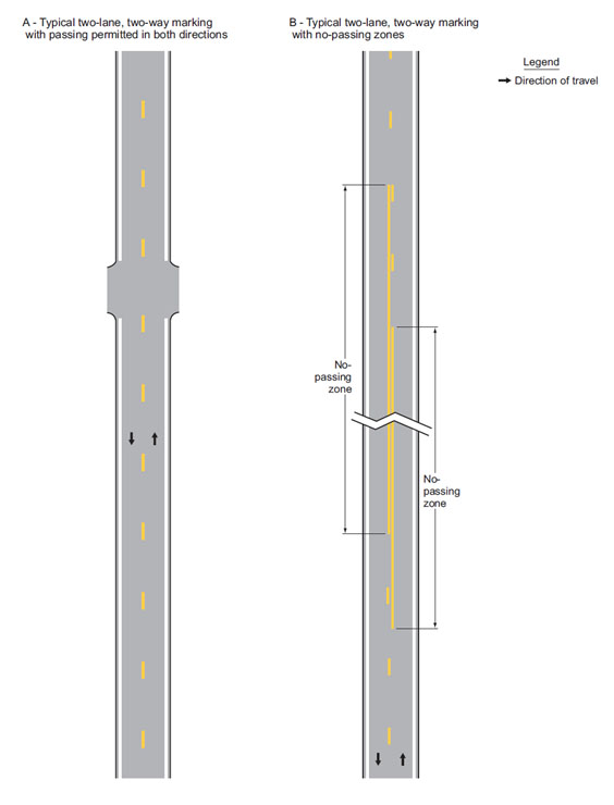
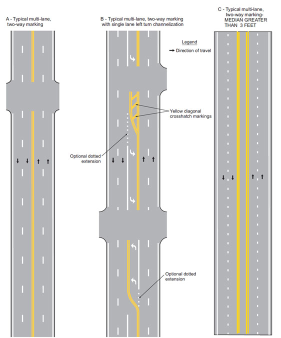
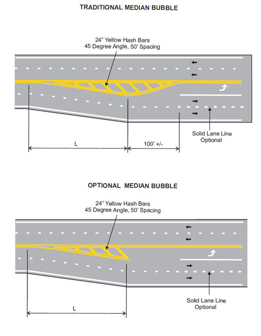

Standard. In no case shall a no passing zone be less than 500 ft. long. If the calculated no passing zone is less than 500 ft., an additional length of marking shall be added to the leading end of the zone to lengthen it to the full 500 feet.
On three-lane roadways where the direction of travel in the center lane transitions from one direction to the other, a no-passing buffer zone shall be provided in the center lane as shown in Figure 903.13.24 Typical Signing for Passing Lanes. A lane transition shall be provided at each end of the buffer zone.
The buffer zone shall be a flush median island formed by two sets of double yellow centerline markings that is at least 50 ft. long.
Guidance. For three-lane roadways having a posted or statutory speed limit of 45 mph or greater, the lane transition taper length should be computed by the formula L = WS for speeds in mph. For roadways where the posted or statutory speed limit is less than 45 mph, the formula L = WS2/60 for speeds in mph should be used to compute taper length. Under both formulas, L equals the taper length in feet, W equals the width of the center lane or offset distance in feet, and S equals the 85th-percentile speed or the posted or statutory speed limit, whichever is higher.
Standard. The minimum lane transition taper length shall be 100 ft. in urban areas and 200 ft. in rural areas.
When used to delineate between climbing lanes on long grades, a no passing zone shall be provided on the taper as well as a distance of 1/2 the taper length in advance of and following the taper.
Guidance. The tangent line should not extend beyond the right-of-way line. Consideration should be given to vegetation or any other seasonal variations when determining the locations of no passing zones (see Fig. 620.2.2.2.1, Method of Locating and Determining the Limit of No-Passing Zones at Curves).
When performing a speed study, an attempt should be made to complete a minimum of 1 study per 10-mile section of roadway, each at a typical section of the roadway. This spacing may vary depending on the degree of uniformity, varying geometrics, cross sections and roadside development. Generally, the criteria determined for a route should be consistent throughout its entire length, without fluctuation due to short changes in terrain that could produce lower speeds. Substantial sections of roadway that have been reconstructed, and thereby provide an increased prevailing speed, should be considered independently of the overall route.
Support. The beginning of a no-passing zone at point “a” in Fig. 620.2.2.2.1, Method of Locating and Determining the Limit of No-Passing Zones at Curves is that point where the sight distance first becomes less than that specified in Table 620.2.2.1 Minimum Passing Sight Distances for No-Passing Zone Markings. The end of the no-passing zone at point “b” in Fig. 620.2.2.2.1 Method of Locating and Determining the Limit of No-Passing Zones at Curves is that point at which the sight distance again becomes greater than the minimum specified.
The values of the minimum passing sight distance that are shown in Table 620.2.2.1 are for operational use in marking no-passing zones and are less than the values that are suggested for geometric design by AASHTO's A Policy on Geometric Design of Highways and Streets.
Guidance. The lane delineation between the climbing lanes provided on long grades, and the descending lane, should be accomplished using centerline markings. In these cases, if the conditions are adequate, a passing zone should be provided for traffic traveling in the single, down grade, lane. A no passing zone should be provided for the length of the climbing lanes for traffic traveling up grade. The up grade climbing lanes should be delineated from each other using a white broken line (see Fig. 620.2.9.2 Standard Pavement Markings for Climbing Lanes).
620.2.2.1 Establishing and Recording No Passing Zones
Standard. The establishment of no passing zones shall be accomplished using two vehicles maintaining a predetermined distance. This distance will mark the beginning and end of the no passing zone section where a target, 3.5 ft. above the road surface on the lead vehicle is just out of sight of the driver of the trailing vehicle, who's eye level is 3.5 ft. above the road surface. The use of a highly visible target, such as a flashing amber light, is recommended.
Guidance. The distance between the vehicles should be maintained constant and equal to the minimum passing sight distance value being used. A printed log of the no passing zone should be kept by the district office and copies given to the regional maintenance superintendents so no passing zones can be relocated after maintenance operations.
Option. Once determined, the beginning and end of no passing zones may be marked on the pavement by using an aerosol spray paint or a paint brush.
Standard. MoDOT has made available to the districts an electronic system that shall be used in documenting no-passing zones.
| 85th Percentile of Posted or Statutory Speed Limit (mph) | Minimum Passing Sight Distance (ft.) |
|---|---|
| 25 | 450 |
| 30 | 500 |
| 35 | 550 |
| 40 | 600 |
| 45 | 700 |
| 50 | 800 |
| 55 | 900 |
| 60 | 1,000 |
| 65 | 1,100 |
| 70 | 1,200 |
620.2.2.2 Centerline Markings On Bridges
Standard. The centerline markings on bridges, having a clear roadway width of 16 ft. or greater, shall be the same as that marked on the adjoining roadway.
Centerline markings shall not be placed on one lane bridges. When dealing with this type of bridge, the centerline markings shall stop a distance of five 500 ft. from each edge of the bridge deck. Therefore, the length of surface not receiving centerline marking shall be 1,000 ft. plus the length of the bridge deck. These bridges will, however, receive the appropriate one-lane bridge markings (see Edgeline Pavement Markings (MUTCD Section 3B.06)).
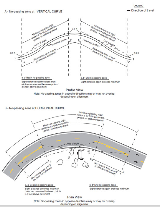


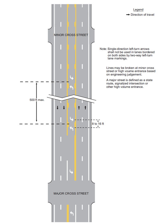
620.2.3 Other Yellow Longitudinal Pavement Markings (MUTCD Section 3B.03)
Standard. If reversible lanes are used, the lane line pavement markings on each side of reversible lanes shall consist of a normal broken double yellow line to delineate the edge of a lane in which the direction of travel is reversed from time to time, such that each of these markings serve as the centerline markings of the roadway during some period (see Example of Reversible Lane Marking Application)).
Signs (see REVERSIBLE LANE CONTROL Signs)), lane-use control signals (see Chapter 4M of MUTCD), or both shall be used to supplement reversible lane pavement markings.
If a two-way left-turn lane that is never operated as a reversible lane is used, the lane line pavement markings on each side of the two-way left-turn lane shall consist of a normal broken yellow line and a normal solid yellow line to delineate the edges of a lane that can be used by traffic in either direction as part of a left-turn maneuver. These markings shall be placed with the broken line toward the two-way left-turn lane and the solid line toward the adjacent traffic lane as shown in Example of Two-Way, Left-Turn Marking Applications.
White two-way left-turn lane-use arrows shall be used to indicate the proper use of these lanes. The left turn arrows shall be installed in pairs, one arrow per direction.
Option. Additional signs may be installed after major intersections, or in situations that require additional emphasis of the proper use of this lane. Two way left turn lanes may be established by the district if the roadway meets all of the guidelines listed in Two-Way Left-Turn Lanes.
Guidance. The pairs of arrows should be installed a maximum of 500 ft. apart, with the two arrows in the pair being 8 to 16 ft. apart (See Fig. 620.2.2.2.4, Example of Two-Way, Left-Turn Marking Applications) on the route containing this type of lane.
Signs should be used in conjunction with the two-way left turn markings (see TWO-WAY LEFT TURN ONLY/CENTER LANE ONLY Signs).
Standard. If a continuous flush median island formed by pavement markings separating travel in opposite directions is used, two sets of double solid yellow lines shall be used to form the island as shown in Fig. 620.2.2.0.2, Examples of Four-Lane Undivided, Two-Way Marking Applications and Fig. 620.2.2.2.1, Examples of Three-Lane, Two-Way Marking for Changing Direction of the Center Lane. Other markings in the median island area shall also be yellow, except crosswalk markings which shall be white (see Crosswalk Markings).
Option. Markings may be used to form islands as shown in Fig. 620.2.2.0.3 Marking for Median Islands for Left Turn Bays.
620.2.4 White Lane Line Pavement Markings and Warrants (MUTCD Section 3B.04)
Standard. When used, lane line pavement markings delineating the separation of traffic lanes that have the same direction of travel shall be white.
Lane line markings shall be used on all freeways and interstate highways.
Lane line markings shall be used on all roadways that are intended to operate with two or more adjacent traffic lanes in the same direction of travel, except as required for reversible lanes.
Guidance. Lane line markings should also be used at congested locations where the roadway will accommodate more traffic lanes with lane line markings than without the markings.
The lane width delineated by lane line pavement markings should not be less than 10 ft., with 12 ft. as the standard dimension.
Standard. White lane line, intermittent pavement markings on new concrete pavements shall be enhanced by the use of contrast markings.
Support. Examples of lane line markings are shown in the following figures:
Standard. Where crossing the lane line markings with care is permitted, the lane line markings shall consist of a normal broken white line (See EPG 620.1.6 Functions, Widths and Patterns of Longitudinal Pavement Markings (MUTCD Section 3A.06)).
A dotted white line marking shall be used as the lane line to separate a through lane that continues beyond the interchange or intersection from an adjacent lane for any of the following conditions:
- A. A deceleration or acceleration lane,
- B. A through lane that becomes a mandatory exit or turn lane,
- C. An auxiliary lane 2 miles or less in length between an entrance ramp and an exit ramp, or
- D. An auxiliary lane 1 mile or less in length between two adjacent intersections.
For exit ramps with a parallel deceleration lane, a normal width dotted white lane line shall be installed from the upstream end of the full-width deceleration lane to the theoretical gore or to the upstream end of a solid white lane line, if used, that extends upstream from the theoretical gore as shown in "A" of Fig. 620.2.5.1 and "C" of Fig. 620.2.5.2.
Option. For exit ramps with a parallel deceleration lane, a normal width dotted white line extension may be installed in the taper area upstream from the full-width deceleration lane as shown in "A" of Fig. 620.2.5.1 and "C" of Fig. 620.2.5.2.
For an exit ramp with a tapered deceleration lane, a normal width dotted white line extension may be installed from the theoretical gore through the taper area such that it meets the edgeline at the upstream end of the taper as shown in "A" of Fig. 620.2.5.1.
Standard. For entrance ramps with a parallel acceleration lane, a normal width dotted white lane line shall be installed from the theoretical gore or from the downstream end of a solid white lane line, if used, that extends downstream from the theoretical gore, to a point at least one-half the distance from the theoretical gore to the downstream end of the acceleration taper, as shown in "A" of Fig. 620.2.5.3.
Option. For entrance ramps with a parallel acceleration lane, a normal width dotted white line extension may be installed from the downstream end of the dotted white lane line to the upstream end of the acceleration taper, as shown in "A" of Fig. 620.2.5.3.
For entrance ramps with a tapered acceleration lane, a normal width dotted white line extension may be installed from the downstream end of the channelizing line adjacent to the through lane to the theoretical gore, as shown in "B" of Fig. 620.2.5.3 and Fig 620.2.5.4.
Standard. A wide dotted white lane line shall be used:
- A. As a lane drop marking in advance of lane drops at exit ramps to distinguish a lane drop from a normal exit ramp (see Figs.620.2.5.5, 620.2.5.6 and 620.2.5.7).
- B. In advance of freeway route splits with dedicated lanes (see Fig. 620.2.5.8),
- C. To separate a through lane that continues beyond an interchange from an adjacent
auxiliary lane between an entrance ramp and an exit ramp (see Fig. 620.2.5.9),
- D. As a lane drop marking in advance of lane drops at intersections to distinguish a lane drop from an intersection through lane (see Fig. 620.2.5.10.1) and
- E. To separate a through lane that continues beyond an intersection from an adjacent auxiliary lane between two intersections (see Fig. 620.2.5.10.2).
Guidance. Lane drop markings used in advance of lane drops at freeway and expressway exit ramps should begin at least 1/2 mile in advance of the theoretical gore or where signing indicates the exit only condition.
On the approach to a multi-lane exit ramp having an optional exit lane that also carries through traffic, lane line markings should be used as illustrated in Fig. 620.2.5.6. In this case, if the right-most exit lane is an added lane such as a parallel deceleration lane, the lane drop marking should begin at the upstream end of the full-width deceleration lane, as shown in Fig. 620.2.5.2.
Lane drop markings used in advance of lane drops at intersections should begin a distance in advance of the intersection that is determined by engineering judgment as suitable to enable drivers who do not desire to make the mandatory turn to move out of the lane being dropped prior to reaching the queue of vehicles that are waiting to make the turn. The lane drop marking should begin no closer to the intersection than the most upstream regulatory or warning sign associated with the lane drop.
The dotted white lane lines that are used for lane drop marking and that are used as a lane line separating through lanes from auxiliary lanes should consist of line segments that are 3 ft. long separated by 9 ft. gaps.
Support. EPG 620.2.20 contains information regarding other markings that are associated with lane drops, such as lane-use arrow markings and ONLY word markings.
EPG 620.2.9 contains information about the lane line markings that are to be used for transition areas where the number of through lanes is reduced.
Standard. Where crossing the lane line markings is discouraged, the lane line markings shall consist of a normal or wide solid white line.
Option. Where it is intended to discourage lane changing on the approach to an exit ramp, a wide solid white lane line may extend upstream from the theoretical gore or, for multiple lane exits, as shown in Fig. 620.2.5.6, for a distance that is determined by engineering judgment.
A solid lane line may also be used in lieu of the broken lane line to accentuate the lane marking in critical areas, such as, to separate a turn lane from the main traffic lanes at an intersection or to discourage lane changing at the approaches to intersections.
Where lane changes might cause conflicts, a wide or normal solid white lane line may extend upstream from an intersection.
In the case of a lane drop at an exit ramp or intersection, such a solid white line may replace a portion, but not all of the length of the wide dotted white lane line.
Support. EPG 620.2.9 contains information about the lane line markings that are to be used for transition areas where the number of through lanes is reduced.
Guidance. On approaches to intersections, a solid white lane line marking should be used to separate a through lane from an added mandatory turn lane.
Option. On approaches to intersections, solid white lane line markings may be used to separate adjacent through lanes or adjacent mandatory turn lanes from each other.
Where the median width allows the left-turn lanes to be separated from the through lanes to give drivers on opposing approaches a less obstructed view of opposing through traffic, white pavement markings may be used to form channelizing islands as shown in Figure 2B-17 of the MUTCD.
Solid white lane line markings may be used to separate through traffic lanes from auxiliary lanes, such as an added uphill truck lane or a preferential lane.
Wide solid lane line markings may be used for greater emphasis.
Standard. Where crossing the lane line markings is prohibited, the lane line markings shall consist of a solid double white line (see Fig. 620.2.5.11).
Guidance. When considering the use of double solid white lines to prohibit crossing all of the following criteria should be considered:
- 1. There has to be an identifiable need, such as crash history that the use of double solid white lines would expect to correct.
- 2. There needs to be a local ordinance supporting the crossing restriction and enforcement.
- 3. There needs to be proper signing of the restriction in advance and at the restricted area along with sufficient distance for motorist who need to properly change lanes prior to the start of the restriction.
- 4. Approval of the State Traffic Engineer is required before implementation.
Standard. Lane lines shall be offset approximately 2 in. to the right of the longitudinal joint. These 2 in. shall be the space between the longitudinal joint and the left edge of the lane line.
620.2.5 Other White Longitudinal Pavement Markings (MUTCD Section 3B.05)
Standard. A channelizing line shall be a wide or double solid white line.
Option. Channelizing lines may be used to form channelizing islands where traffic traveling in the same direction is permitted on both sides of the island.
Standard. Channelizing lines used to mark gores shall be wide solid white lines.
Other pavement markings in the channelizing island area shall be white.
Support. Examples of channelizing line applications are shown in the following figures:
for Exit Ramp Markings (Sheet 1 of 2) (MUTCD 3B-8)
Channelizing lines at exit ramps as shown in Fig. 620.2.5.1, Examples of Dotted Line and Channelizing Line Application for Exit Ramp Markings (Sheet 1 of 2) and Fig. 620.2.5.2, Examples of Dotted Line and Channelizing Line Application for Exit Ramp Markings (Sheet 2 of 2) define the neutral area, direct exiting traffic at the proper angle for smooth divergence from the main lanes into the ramp, and reduce the probability of colliding with objects adjacent to the roadway.
Channelizing lines at entrance ramps as shown in Fig. 620.2.5.3, Examples of Dotted Line and Channelizing Line Application for Entrance Ramp Markings (Sheet 1 of 2) promote orderly and efficient merging with the through traffic.
Standard. For all exit ramps and for entrance ramps with parallel acceleration lanes, channelizing lines shall be placed on both sides of the neutral area (see Fig. 620.2.5.1, Fig. 620.2.5.2, Fig. 620.2.5.5, Fig. 620.2.5.6, Fig. 620.2.5.7, Fig. 620.2.5.8, Fig. 620.2.5.9 and "A" in Fig. 620.2.5.3.
For entrance ramps with tapered acceleration lanes, channelizing lines shall be placed along both sides of the neutral area to a point at least one-half of the distance to the theoretical gore (see Fig. 620.2.5.4).
Option. For entrance ramps with tapered acceleration lanes, the channelizing lines may extend to the theoretical gore as shown in Fig. 620.2.5.3.

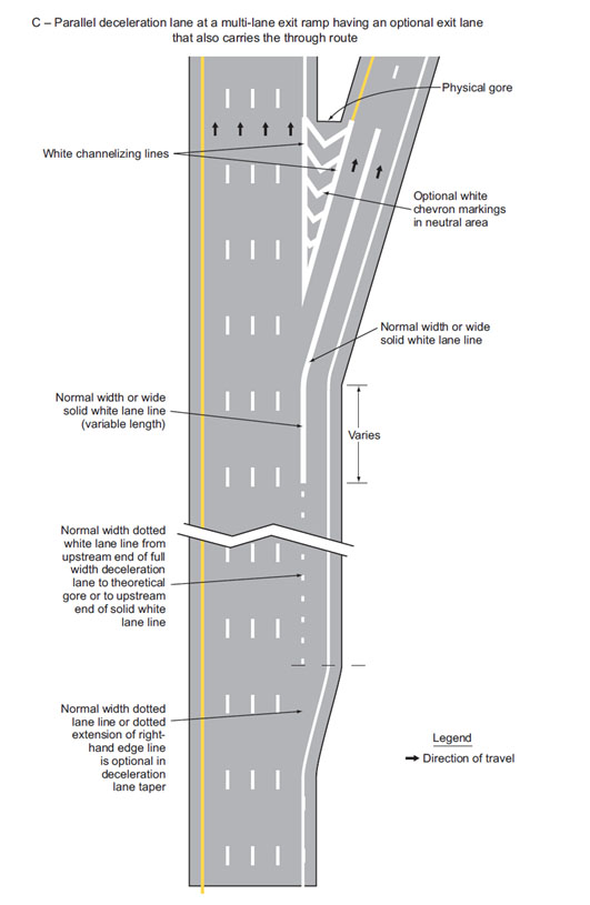
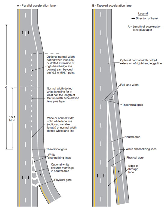

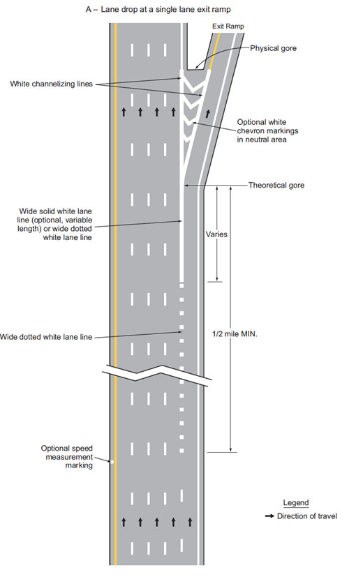
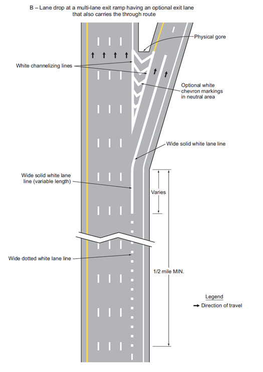
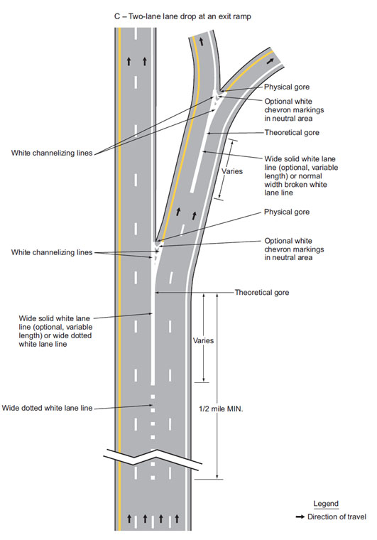
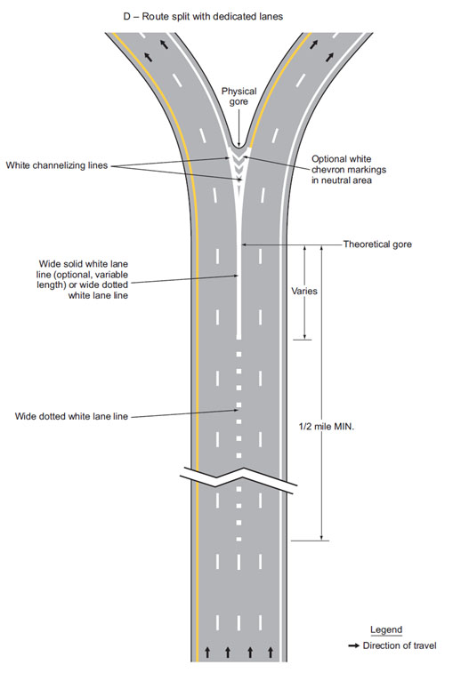
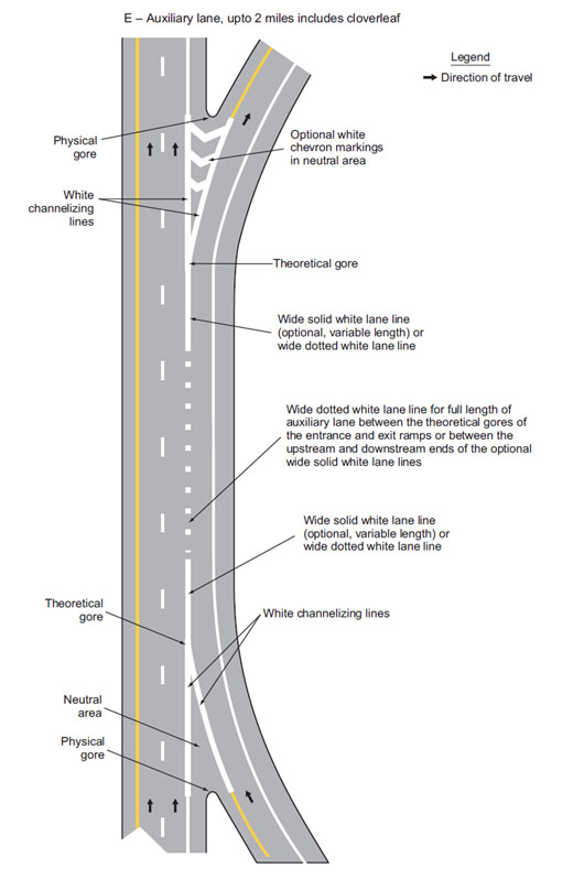
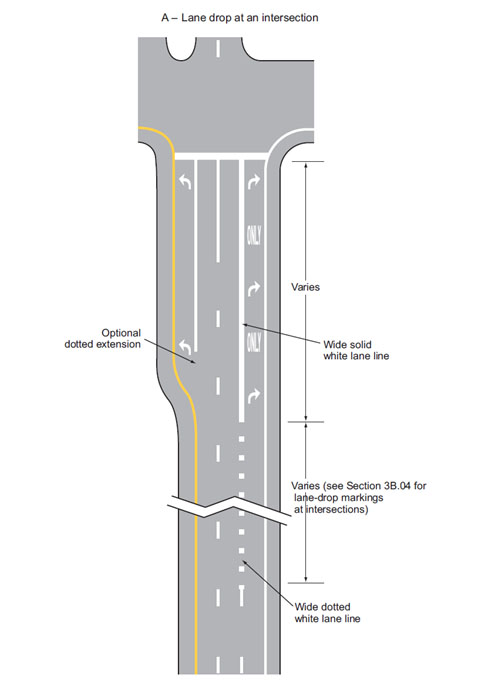
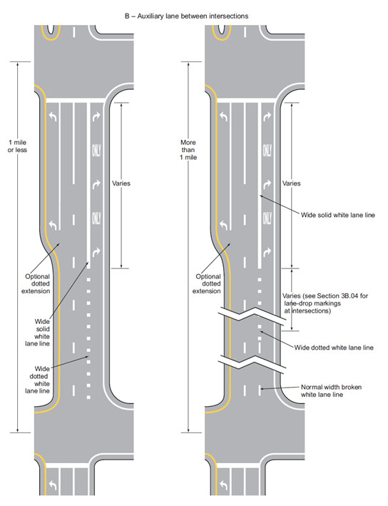
Option. White chevron crosshatch markings (see EPG 620.2.24) may be placed in the neutral area of exit and entrance ramp gores for special emphasis as shown in Figs. 620.2.5.1 and 620.2.5.2, Figs. 620.2.5.5 through 620.2.5.9 and "A" of Fig. 620.2.5.3. The channelizing lines and the optional chevron crosshatch markings at exit ramp and entrance ramp gores may be supplemented with white retroreflective or internally illuminated raised pavement markers (see EPG 620.2.11) for enhanced nighttime visibility.
Guidance. The right edge of the acceleration lane edgeline should be continuous with the right edge of the gore stripe to provide a smooth, uninterrupted edgeline.
Options. In areas of limited sight distance due to vertical and/or horizontal curves, an edgeline extension may be used to delineate acceleration and deceleration lanes.
Standard. When entrance and exit ramp pavements are adjacent to each other, a double normal 4 in. solid yellow line extending from the points of channelization shall be used.
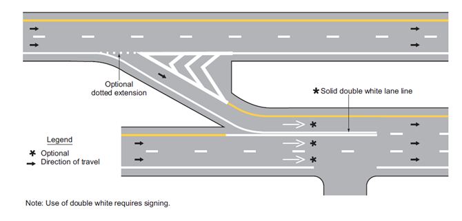
620.2.6 Edgeline Pavement Markings (MUTCD Section 3B.06)
Standard. If used, edgeline pavement markings shall delineate the right or left edges of a roadway.
Except for dotted edgeline extensions (see EPG 620.2.8), edgeline markings shall not be continued through intersections or major driveways.
If used on the roadways of divided highways or one-way streets, or on any ramp in the direction of travel, left edgeline pavement markings shall consist of a normal solid yellow line to delineate the left-hand edge of a roadway or to indicate driving or passing restrictions left of these markings.
If used, right edgeline pavement markings shall consist of a normal solid white line to delineate the right-hand edge of the roadway.
Guidance. The edgeline at the intersection of an at-grade crossing on a divided highway should begin and end at the taper points (See Fig. 620.2.7 Edgeline Striping for At-Grade Intersections).
Option. Edgeline extension lines may be used at the district's discretion.
Guidance. Edgeline markings should not be broken for driveways or minor intersecting roads (See Fig. 620.2.7).
Permanent marking material should be used for marking the edgeline extension.
| 1) Expand the installation of edgelines | |||
| · Install edgelines on routes that are 20 ft. or wider and have AADT greater than 400 (previous policy was AADT greater than 1000) | |||
| - Economic Recovery Routes | |||
| - Minor Road “WOW” Routes | |||
| · An additional 7,600 centerline miles will be added to the striping program (98% of VMT would then be on a route with an edgeline) | |||
| · Districts may exempt routes based on the condition of the pavement (the route should be in good condition) | |||
| · Implement over four years. Re-stripe no more than every other year by policy | |||
| 2) Enhance the visibility of all warning signs | |||
| · Use fluorescent yellow sheeting for all warning signs | |||
| · Replace existing warning signs at the end of their useful life | |||
| 3) Expand the installation of chevrons on curves | |||
| · Install chevron signs on curves that have an advisory speed that is at least 15 MPH less than the posted speed limit. (If the posted speed limit is less than 45 MPH, and it is in an incorporated area, the decision to install chevrons will be based on engineering judgment.) | |||
| - Major Routes | |||
| - Economic Recovery Routes | |||
| - Minor Road “WOW” Routes | |||
| 4) Remove obstacles within 30 ft. of the travelway and at other critical locations | |||
| · Remove trees (not to extend past MoDOT right of way line) on major roads | |||
| · Remove trees (not to extend past MoDOT right of way line) on roads that are in the minor road WOW program (4,500 miles) and economic recovery routes | |||
| · Remove trees within the right of way within critical locations (i.e. outside of horizontal curves, crash experience, etc.) | |||
| · Improve the slopes for driveway culverts/pipes at critical locations | |||
Support. Edgeline markings have unique value as visual references to guide road users during adverse weather and visibility conditions.
Option. Wide solid edgeline markings may be used for greater emphasis.
620.2.7 Warrants for Use of Edge Lines (MUTCD Section 3B.07)
Standard. Edgeline markings shall be placed on all divided highways and all routes with a weighted AADT of 400 or greater and a minimum pavement width of 20 feet.
Guidance. Routes that meet the 400 AADT and are in incorporated areas or recognized communities should not receive edgeline if there are curbs. Also, if where there are large undefined entrances, the edgelines may be omitted.
Exceptions should be considered if the district determines edgelines are warranted for the sake of continuity or if operational aspects could be adversely affected if edgelines are omitted.
Standard. Edgelines on routes with weighted AADT between 400 and 1,000 shall be added to the program by December 31, 2012.
Guidance. The edgelines on minor roads with a weighted AADT between 400 and 1,000, should only be striped once every two years unless conditions warrant they be striped more often.
Option. Edgeline markings may be excluded, based on engineering judgment, for reasons such as if the traveled way edges are delineated by curbs, parking or other markings or where the pavement is not in good condition.
If a bicycle lane is marked on the outside portion of the traveled way, the edgeline that would mark the outside edge of the bicycle lane may be omitted.
Edgeline markings may be used where edge delineation is desirable to minimize unnecessary driving on paved shoulders or on refuge areas that have lesser structural pavement strength than the adjacent roadway.
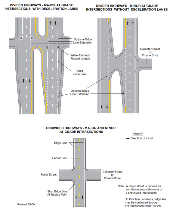
620.2.7.1 Bridge Edgeline
Standard. Bridges that are located on routes authorized for edgeline shall be striped in accordance with the following classifications (see Fig. 620.2.7.1.1 and Fig. 620.2.7.1.2, Bridge Edgeline Striping):
- A. Non-shoulder width bridges that have been constructed with a deck less than 2 ft. wider than the adjacent roadway on each side of the pavement shall not have the edgeline placed on the bridge deck. The edgeline shall end on the adjacent roadway 50 ft. from the bridge deck.
- B. Bridges wider than the roadway pavement by more than 2 ft. on each side shall receive edgeline that will be continuous with that of the adjoining roadway.
- C. Three lane bridges designed and constructed with an additional lane for future use shall be marked as a two lane bridge. The edgeline in these cases shall not be offset to provide for the usage of the third lane and will be continuous across the bridge.
- D. One lane bridges, weight restricted, have a reduced driving surface due to an inability to carry the weight of two lanes of traffic. These bridges shall be marked using a wide white edgeline that forms a 12 ft. travel lane on the bridge deck. These edgelines shall then taper from the edge of the bridge deck 200 ft. to the edge of the roadway pavement. The centerline marking, if applicable, shall end 500 ft. from the end of the bridge deck.
- E. One Lane Bridges, Width Restriction, having a clear traveling surface 16 ft. or less shall be marked using a wide white edgeline that forms a 12 ft. travel lane on the bridge deck. These edgelines shall then taper from the edge of the bridge deck 200 ft. to the edge of the roadway pavement. The centerline marking, if applicable, shall end 500 ft. prior to the bridge deck.
Guidance. Special attention should be given to all bridges whose shoulders are 2 ft. or wider than the shoulders of the adjacent roadway.
Standard. If bridges whose shoulders are 2 ft. or wider than the shoulders of the adjacent roadway are on routes authorized for centerline marking, but not edgeline marking they shall be edgelined to delineate the travel way of the bridge. The edgeline marking for these bridges shall begin 500 ft. ahead of, and end 500 ft. beyond, the bridge deck, and are intended to guide vehicles from the wider bridge deck to the narrower adjacent roadway. (See Fig. 620.2.7.1.1 and Fig. 620.2.7.1.2).
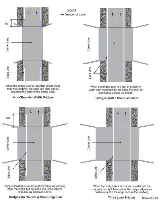
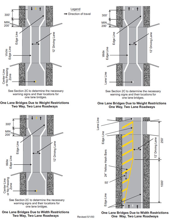
620.2.8 Extensions Through Intersections or Interchanges (MUTCD Section 3B.08)
Standard. Except as provided in the Option, below, pavement markings extended into or continued through an intersection or interchange area shall be the same color and at least the same width as the line markings they extend.
Intersections that provide dual left turn lanes shall have extension lines traffic can follow through the intersection except as provided in the Support, below. These lines shall be marked with normal white skips, 2 ft. long and separated by 4 ft. gaps, and shall follow the appropriate turning radius of the intersection. This line shall begin at the solid white lane line of the left turn bay and end at the lane line delineating the lanes the traffic is being channelized to.
Option. A normal lane line may be used to extend a wide line through an intersection.
Support. Exceptions will be allowed when an intersection lacks adequate space to place extension lines for dual left turn lanes when an intersection lacks adequate space to place these lines for opposing left turn movements.
Guidance. Long life pavement markings should be used for extensions.
An attempt should be made to keep the painted portion of this line out of the wheel tracks to promote longer life.
Where highway design or reduced visibility conditions make it desirable to provide control or to guide vehicles through an intersection or interchange, such as at offset, skewed, complex, or multi-legged intersections, on curved roadways, where multiple turn lanes are used, or where offset left turn lanes might cause driver confusion, dotted line extension markings consisting of 2 ft. line segments and 4 ft. gaps should be used to extend longitudinal line markings through an intersection or interchange area.
Option. Dotted edgeline extensions may be placed through intersections or major driveways.
Guidance. Where greater restriction is required, solid lane lines or channelizing lines should be extended into or continued through intersections or major driveways.
Standard. Solid lines shall not be used to extend edgelines into or through major intersections or major driveways.
Guidance. Where a double line is extended through an intersection, a single line of equal width to one of the lines of the double line should be used.
To the extent possible, pavement marking extensions through intersections should be designed in a manner that minimizes potential confusion for drivers in adjacent or opposing lanes.
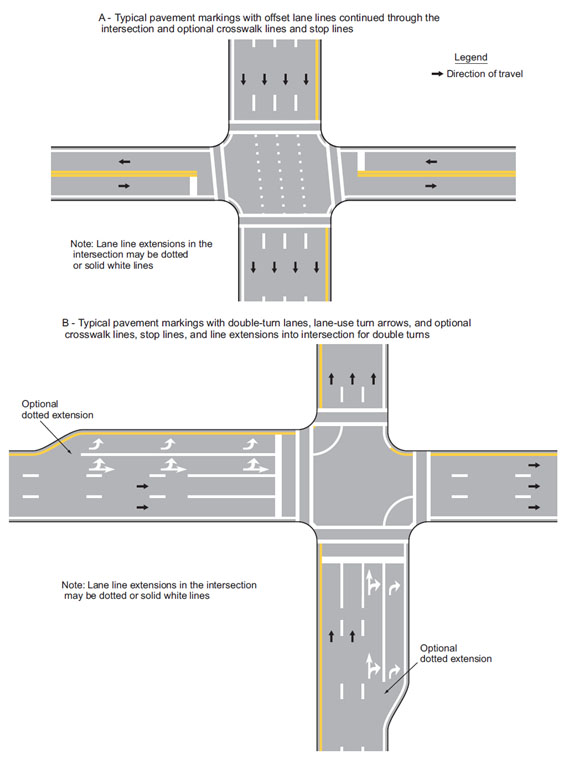

620.2.9 Lane Reduction Transition Markings (MUTCD Section 3B.09)
Support. Lane-reduction transition markings are used where the number of through lanes is reduced because of narrowing of the roadway or because of a section of on-street parking in what would otherwise be a through lane. Lane-reduction transition markings are not used for lane drops.
Standard. Except as provided in the Option, below, where pavement markings are used, lane reduction transition markings shall be used to guide traffic through transition areas where the number of through lanes is reduced, as shown in Fig. 620.2.9.1, Examples of Applications of Lane-Reduction Transition Marking. On two-way roadways, no-passing zone markings shall be used to prohibit passing in the direction of the convergence, and shall continue through the transition area.
Option. On low-speed urban roadways where curbs clearly define the roadway edge in the lane-reduction transition, or where a through lane becomes a parking lane, the edgeline and/or delineators shown in Fig. 620.2.9.1 may be omitted as determined by engineering judgment.
Standard. For roadways having a posted or statutory speed limit of 45 mph or greater, the transition taper length for a lane reduction shall be greater or equal to the length computed by the formula L = WS.
Guidance. For roadways where the posted or statutory speed limit is less than 45 mph, the formula should be used to compute taper length.
Support. Under both formulas, L equals the taper length in ft., W equals the width of the offset distance in ft., and S equals the 85th-percentile speed or the posted or statutory speed limit, whichever is higher.
Guidance. Where observed speeds exceed posted or statutory speed limits, longer tapers should be used.
Option. On new construction, where no posted or statutory speed limit is established, the design speed may be used in the transition taper length formula.
Guidance. Lane line markings should be discontinued one-quarter of the distance between the Lane Ends sign (see LANE END Signs) and the point where the transition taper begins.
Except as provided in the Option, above, for low-speed urban roadways, edgeline markings should be installed from the location of the warning sign to beyond the beginning of the narrower roadway.
Support. Pavement markings at lane reduction transitions supplement the standard signs or delineators. See EPG 620.2.20, Pavement Word and Symbol Markings for provisions regarding use of lane-reduction arrows.
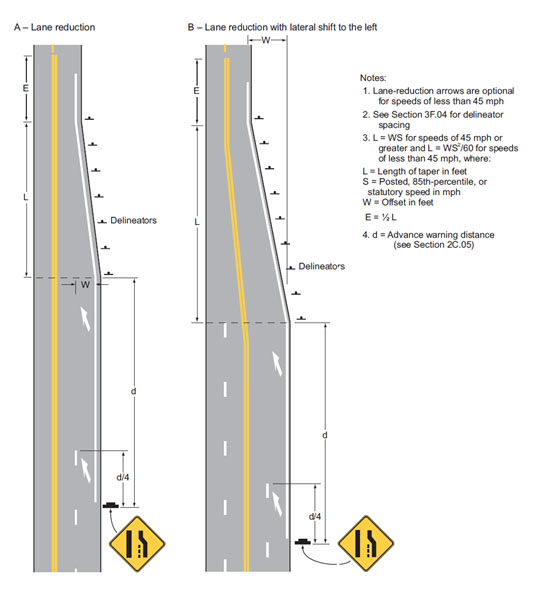
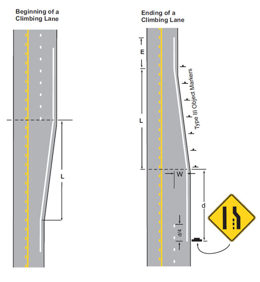
620.2.10 Approach Markings for Obstructions (MUTCD Section 3B.10)
Standard. Pavement markings shall be used to guide traffic away from fixed obstructions within a paved roadway. Approach markings for bridge supports, refuge islands, median islands, and raised channelization islands shall consist of a tapered line or lines extending from the centerline or the lane line to a point 1 to 2 ft. to the right-hand side, or to both sides, of the approach end of the obstruction (see Fig. 620.2.10.2 Examples of Applications of Markings for Obstructions in the Roadway).
All lines used as obstruction pavement markings shall be no less than 4 in. and no more than 24 in. wide.
For roadways having a posted or statutory speed limit of 45 mph or greater, the taper length of the tapered line markings shall be computed by the formula L = WS.
Guidance. For roadways where the posted or statutory speed limit is less than 45 mph, the formula for speeds in mph shall be used to compute taper length.
Support. Under both formulas, L equals the taper length in ft., W equals the width of the offset distance in ft. and S equals the 85th-percentile speed or the posted or statutory speed limit, whichever is higher.
Standard. The minimum taper length shall be 100 ft. in urban areas and 200 ft. in rural areas.
Support. Examples of approach markings for obstructions in the roadway are shown in Fig. 620.2.10.2 Examples of Applications of Markings for Obstructions in the Roadway.
Option. Where observed speeds exceed posted or statutory speed limits, longer tapers may be used.
Unique situations may require special markings or warning devices.
Standard. If traffic is required to pass only to the right of the obstruction, the markings shall consist of a two-direction no-passing zone marking at least twice the length of the diagonal portion as determined by the appropriate taper formula (see Fig. 620.2.10.2 Examples of Applications of Markings for Obstructions in the Roadway.
Option. If traffic is required to pass only to the right of the obstruction, yellow diagonal crosshatch markings (see EPG 620.2.24 may be placed in the flush median area between the no-passing zone markings as shown in Fig. 620.2.10.2. Other markings, such as yellow delineators, yellow channelizing devices, yellow raised pavement markers, and white crosswalk pavement markings, may also be placed in the flush median area.
Standard. If traffic can pass either to the right or left of the obstruction, the markings shall consist of two normal channelizing lines diverging from the lane line, one to each side of the obstruction. In advance of the point of divergence, a wide solid white line or normal solid double white line shall be extended in place of the broken lane line for a distance equal to the length of the diverging lines (see Fig. 620.2.10.2).
If diagonal lines, yellow or white are used, these markings shall be a minimum of 24 in. wide and slope away from the direction traffic is traveling in (see Fig. 620.2.10.2).
When an obstruction lies in the direct line of traffic, it shall be marked.
Option. If traffic can pass either to the right or left of the obstruction, additional white markings may be placed in the flush median area between the channelizing lines as shown in Fig. 620.2.10.2. Other markings, such as white delineators, white channelizing devices, white raised pavement markers, and white crosswalk markings may also be placed in the flush median area.
Option. The obstruction and marking may, if possible, be illuminated by overhead lighting that will adequately light the object without throwing a glare in the face of traffic approaching from either direction.
Standard. Reflective object markers shall be used.
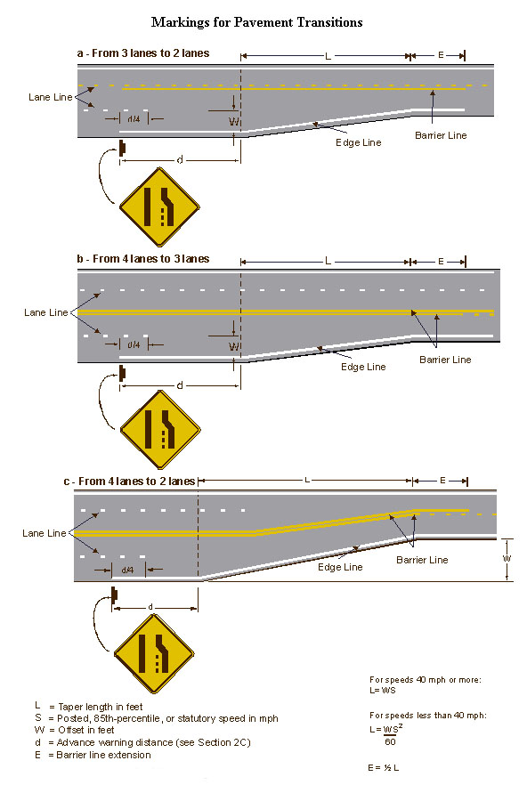
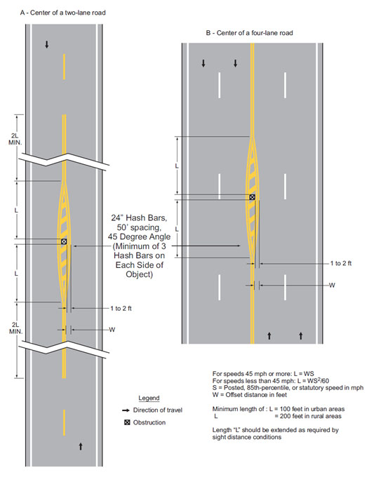

620.2.11 Raised Pavement Markers (MUTCD Section 3B.11)
Support. There are two types of raised pavement markers, temporary and snowplowable. There are also two types of temporary markers. The Type 1 temporary marker is used on surface treatment projects and is applied before the surface treatment is applied. Type 1 temporary markers are also used for temporary edgeline marking and may be used as part of the "cluster marking" for lane lines on divided highways. The Type 2 temporary marker may be used on final surfaces on paving projects. The Type 2 markers are also part of the "cluster marking" for lane lines on divided highways. Snowplowable raised pavement markers are considered to be long life marking application.
MoDOT is responsible for the maintenance of snowplowable raised pavement markers. This maintenance involves the replacement of the reflective lenses that are inlaid into the castings and checking that the castings are firmly in the pavement.
Standard. The color of raised pavement markers under both daylight and nighttime conditions shall conform to the color of the marking for which they serve as a positioning guide, or for which they supplement or substitute.
No new snowplowable raised pavement markers will be installed on MoDOT roads.
Snowplowable raised pavement markers that are found to be loose in the pavement shall be removed.
Option. The side of a raised pavement marker that is visible to traffic proceeding in the wrong direction may be red (see EPG 620.1.5 Colors).
Retroreflective or internally illuminated raised pavement markers may be used in the roadway immediately adjacent to curbed approach ends of raised medians and curbs of islands, or on top of such curbs (see EPG 620.2.23).
Support. Retroreflective and internally illuminated raised pavement markers are available in mono-directional and bidirectional configurations. The bidirectional marker is capable of displaying the applicable color for each direction of travel.
Standard. When used, internally illuminated raised pavement markers shall be steadily illuminated and shall not be flashed.
Support. Flashing raised pavement markers are considered to be In-Roadway Lights (see MUTCD Chapter 4N).
Guidance. The spacing of raised pavement markers used to supplement or substitute for other types of longitudinal markings should correspond with the pattern of broken lines for which the markers supplement or substitute.
A visual inspection should be performed in the spring of the year to determine the condition and the number of reflectors needed to maintain the markers. The replacement schedule should be determined by the district to best use available time and personnel. This survey should also include the condition of the castings in the pavement.
Standard. The value of N for the spacing of raised pavement markers shall equal the length of one line segment plus one gap of the broken lines used on the highway.
The spacing of temporary pavement markers shall be in accordance with Standard Plan 620.
Option. The replacement of defective reflectors may be accomplished under contract.
620.2.12 Raised Pavement Markers as Vehicle Positioning Guides with Other Longitudinal Markings (MUTCD Section 3B.12)
Not used in Missouri.
620.2.13 Raised Pavement Markers Supplementing Other Markings (MUTCD Section 3B.13)
Not used in Missouri.
620.2.14 Raised Pavement Markers Substituting for Pavement Markings (MUTCD Section 3B.14)
Not used in Missouri.
620.2.15 Transverse Markings (MUTCD Section 3B.15)
Standard. Transverse markings, which include shoulder markings, word and symbol markings, arrows, stop lines, yield lines, crosswalk lines, speed measurement markings, speed reduction markings, speed hump markings, parking space markings, and others, shall be white unless otherwise provided herein.
Guidance. Because of the low approach angle at which pavement markings are viewed, transverse lines should be proportioned to provide visibility at least equal to that of longitudinal lines.
Transverse markings should use durable materials for permanent installations.
Support. Particular attention must be given to the maintenance of transverse lines and markings. Due to their placement on the pavement, these markings are subject to constant wear.
620.2.16 Stop and Yield Lines (MUTCD Section 3B.16)
Guidance. Stop lines should be used to indicate the point behind which vehicles are required to stop, in compliance with a traffic control signal.
Option. Stop lines may be used to indicate the point behind which vehicles are required to stop in compliance with a STOP (R1-1) sign, a Stop Here For Pedestrians (R1-5b or R1-5c) sign, or some other traffic control device that requires vehicles to stop, except YIELD signs that are not associated with passive grade crossings.
Yield lines may be used to indicate the point behind which vehicles are required to yield in compliance with a YIELD (R1-2) sign or a Yield Here to Pedestrians (R1-5 or R1-5a) sign.
Standard. Except as provided in MUTCD Section 8B.28, stop lines shall not be used at locations where drivers are required to yield in compliance with a YIELD (R1-2) sign or a Yield Here To Pedestrians (R1-5 or R1-5a) sign or at locations on uncontrolled approaches where drivers are required by State law to yield to pedestrians.
Yield lines shall not be used at locations where drivers are required to stop in compliance with a STOP (R1-1) sign, a Stop Here For Pedestrians (R1-5b or R1-5c) sign, a traffic control signal, or some other traffic control device.
Stop lines shall consist of solid white lines extending across approach lanes to indicate the point at which the stop is intended or required.
Stop lines shall be used in advance of railroad crossings to indicate the appropriate location to stop.
When any crosswalk is installed where a permanent traffic control device is provided, such as a STOP sign or traffic signal, a stop line shall be installed in advance of the crosswalk.
Stop lines shall be 24 in. wide and shall extend across all lanes affected by the traffic control device.
Yield lines (see Fig. 620.2.16, Examples of Yield Line Layouts) shall consist of a row of solid white isosceles triangles pointing toward approaching vehicles extending across approach lanes to indicate the point at which the yield is intended or required. The spacing of triangles in a yield line shall be consistent for that marking.
Guidance. If used, the smaller size yield line should be 16 in. wide by 24 in. tall and should be used on right turn lanes. The larger size yield line should be 24 in. wide by 36 in. tall and should be used on ramps where there is no acceleration lane.
The space between the triangles should be 3 to 6 in. as shown on Standard Plan 620.00.
Yield lines may be considered for those locations where a free right turn lane is developed but there is not an acceleration lane on the intersecting road. Yield lines may also be considered at on ramps with tapered acceleration lanes as shown in Fig. 620.2.5.3, Examples of Dotted Lined and Channelizing Line Applications for Entrance Ramp Markings.
Yield lines may also be used where engineering judgment indicates a need.
Guidance. If used, stop and yield lines should be placed a minimum of 4 ft. in advance of the nearest crosswalk line at controlled intersections, except for yield lines at roundabouts as provided for in EPG 620.3.4 Yield Lines for Roundabouts and at midblock crosswalks. In the absence of a marked crosswalk, the stop line or yield line should be placed at the desired stopping or yielding point, but should not be placed more than 30 ft. nor less than 4 ft. from the nearest edge of the intersecting traveled way. Stop lines should be placed to allow sufficient sight distance to all other approaches to an intersection.
When a stop line is used in conjunction with the STOP sign it should be placed adjacent to, or in line with, the STOP sign.
When a yield line is used in conjunction with the YIELD sign it should be placed adjacent to, or in line with, the YIELD sign.
Stop lines at midblock signalized locations should be placed at least 40 ft. in advance of the nearest signal indication.
If yield or stop lines are used at a crosswalk that crosses an uncontrolled multilane approach, the yield lines or stop lines should be placed 20 to 50 ft. in advance of the nearest crosswalk line, and parking should be prohibited in the area between the yield or stop line and the crosswalk (see Figure 620.2.17.1 Examples of Yield Lines at Unsignalized Midblock Crosswalks).
Standard. If yield (stop) lines are used at a crosswalk that crosses an uncontrolled multi-lane approach, Yield Here To (Stop Here For) Pedestrians (R1-5 series) signs (see EPG 620.2.11 Raised Pavement Markers shall be used).
Guidance. Yield (stop) lines and Yield Here To (Stop Here For) Pedestrians signs should not be used in advance of crosswalks that cross an approach to or departure from a roundabout.
Support. Drivers yielding or stopping too close to crosswalks that cross uncontrolled multi-lane approaches place pedestrians at risk by blocking other drivers’ views of pedestrians and by blocking pedestrians’ view of vehicles approaching in the other lanes.
Option. Stop and yield lines may be staggered longitudinally on a lane-by-lane basis. Refer to "D" of Fig. 620.2.8.2.
Support. Staggered stop lines and staggered yield lines can improve the driver's view of pedestrians, provide better sight distance for turning vehicles and increase the turning radius for left-turning vehicles.
EPG 620.2.28 Stop and Yield Lines at Highway-Rail Grade Crossings contains information regarding the use of stop lines and yield lines at grade crossings.
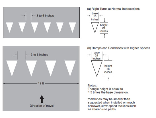
620.2.17 Do Not Block Intersection Markings (MUTCD Section 3B.17)
Option. Do Not Block Intersection markings may be used to mark the edges of an intersection area that is in close proximity to a signalized intersection, railroad crossing or other nearby traffic control that might cause vehicles to stop within the intersection and impede other traffic entering the intersection. If authorized by law, Do Not Block Intersection markings with appropriate signs may also be used at other locations.
Standard. If used, Do Not Block Intersection markings (see Figure 620.2.17.2) shall consist of wide solid white lines that outline the intersection area that vehicles must not block 8 in. to 12 in. wide and white cross-hatching within the intersection area 4 in. to 6 in. wide.
Do Not Block Intersection markings shall be accompanied by one or more DO NOT BLOCK INTERSECTION (DRIVEWAY) (CROSSING) (R10-7) signs (see EPG 903.5.30), one or more DO NOT STOP ON TRACKS (R8-8) signs (see EPG 903.20 Signing for Rail and Light Rail Transit Grade Crossings) or one or more similar signs.
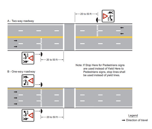
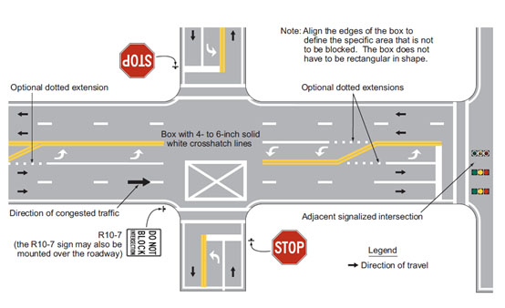
620.2.18 Crosswalk Markings (MUTCD Section 3B.18)
Support. Crosswalk markings provide guidance for pedestrians who are crossing roadways by defining and delineating paths on approaches to and within signalized intersections, and on approaches to other intersections where traffic stops.
In conjunction with signs and other measures, crosswalk markings help to alert road users of a designated pedestrian crossing point across roadways at locations that are not controlled by traffic control signals or STOP or YIELD signs.
At non-intersection locations, crosswalk markings legally establish the crosswalk.
Standard. When crosswalk lines are used, they shall consist of solid white lines that mark the crosswalk. They shall be not less than 6 in. nor greater than 24 in. wide and 6 ft. apart.
If transverse lines are used to mark a crosswalk, the gap between the lines shall not be less than 6 feet. If longitudinal lines are used without transverse lines to mark a crosswalk, the crosswalk shall not be less than 6 ft. wide.
Guidance. Crosswalk lines, if used on both sides of the crosswalk, should extend across the full width of pavement or to the edge of the intersecting crosswalk to discourage diagonal walking between crosswalks (see Standard Plan 620.00).
At locations controlled by traffic control signals or on approaches controlled by STOP or YIELD signs, crosswalk lines should be installed where engineering judgment indicates they are needed to direct pedestrians to the proper crossing path(s).
Crosswalk lines should not be used indiscriminately. An engineering study should be performed before a marked crosswalk installed at a location away from a traffic control signal or STOP or YIELD signs. The engineering study should consider the number of lanes, the presence of a median, the distance from adjacent signalized intersections, the pedestrian volumes and delays, the average annual daily traffic (AADT), the posted or statutory speed limit or 85th-percentile speed, the geometry of the location, the possible consolidation of multiple crossing points, the availability of street lighting and other appropriate factors.
New marked crosswalks alone, without other measures designed to reduce traffic speeds, shorten crossing distances, enhance driver awareness of the crossing, and/or provide active warning of pedestrian presence, should not be installed across uncontrolled roadways where the speed limit exceeds 40 mph and either:
- A. The roadway has four or more lanes of travel without a raised median or pedestrian refuge island and an ADT of 12,000 vehicles per day or greater; or
- B. The roadway has four or more lanes of travel with a raised median or pedestrian refuge island and an ADT of 15,000 vehicles per day or greater.
Support. Chapter 4F of the MUTCD contains information on Pedestrian Hybrid Beacons. Section 4L.03 contains information regarding Warning Beacons to provide active warning of a pedestrian's presence. Section 4N.02 contains information regarding In-Roadway Warning Lights at crosswalks. Chapter 7D contains information regarding school crossing supervision.
Guidance. Because non-intersection pedestrian crossings are generally unexpected by the road user, warning signs (see Non-vehicular Sign (W11-2, W11-7)) should be installed and adequate visibility should be provided by parking prohibitions.
If used, the “Zebra” pedestrian crosswalk marking should consist of longitudinal lines 30 in. wide and spaced 30 in. apart for 10 ft. lanes, 33 in. wide and spaced 33 in. apart for 11 ft. lanes and 36 in. wide and spaced 36 in. apart for 12 ft. lanes.
When longitudinal lines are used to mark a crosswalk, the transverse crosswalk lines should be omitted. The marking design should avoid the wheel paths.
Support. EPG 620.2.16 contains information regarding placement of stop line markings near crosswalk markings.
Option. Where permanent traffic control devices are not provided, speeds are greater than 35 mph or the crosswalk is located in rural locations where they are unexpected, the width of the crosswalk line may be increased up to 24 inches.
Crosswalks may be located mid-block if this placement offers greater safety to the pedestrian than the normal placement at an intersection. In these cases, the “Zebra” pedestrian crosswalk marking may be used for greater emphasis and visibility. This type of marking may also be used at locations where substantial numbers of pedestrians cross without any other traffic control device, at locations where physical conditions are such that added visibility of the crosswalk is desired, or at places where a pedestrian crosswalk might not be expected.
Standard. All school crosswalks authorized by an agreement between the Commission and the school and/or city shall be marked. Crosswalks for schools shall be maintained in a manner that will provide a clearly visible marking at all times.
All school crosswalks shall be marked using both the advance school crosswalk and the school crosswalk sign, refer to EPG 903.19.8 School Sign (S1-1) and Plaques.
Option. When school crosswalks are located mid-block, the “Zebra” pedestrian crosswalk marking may be used for greater emphasis and visibility.
Guidance. Crosswalk markings should be located so that the curb ramps are within the extension of the crosswalk markings.
Support. Detectable warning surfaces mark boundaries between pedestrian and vehicular ways where there is no raised curb. Detectable warning surfaces are required by 49 CFR, Part 37 and by the Americans with Disabilities Act (ADA) where curb ramps are constructed at the junction of sidewalks and the roadway, for marked and unmarked crosswalks. Detectable warning surfaces contrast visually with adjacent walking surfaces, either light-on-dark, or dark-on-light. The Americans with Disabilities Act Accessibility Guidelines for Buildings and Facilities (ADAAG) (see MUTCD Section 1A.11) contains specifications for design and placement of detectable warning surfaces.
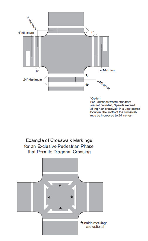
620.2.19 Parking Space Markings (MUTCD Section 3B.19)
Support. Marking of parking space boundaries encourages more orderly and efficient use of parking spaces where parking turnover is substantial. Parking space markings tend to prevent encroachment into fire hydrant zones, bus stops, loading zones, approaches to intersections, curb ramps, and clearance spaces for islands and other zones where parking is restricted. Examples of parking space markings are shown in Fig. 620.2.20.1, Examples of Parking Space Markings.
If the parking lot is not striped, it is not necessary to mark the disabled reserved stall.
Standard. Parking space markings shall be white.
The marking used for disabled parking areas shall be white, except for the curb painting, which shall be blue in color.
If the parking lot is striped, then the required number of disabled stalls shall be marked as follows:
| Total Parking in Lot | Required Minimum Number of Accessible Spaces |
|---|---|
| 1 to 25 | 1 |
| 26 to 50 | 2 |
| 51 to 75 | 3 |
| 76 to 100 | 4 |
| 101 to 150 | 5 |
| 151 to 200 | 6 |
| 201 to 300 | 7 |
| 301 to 400 | 8 |
| 401 to 500 | 9 |
| 501 to 1000 | (2 percent of total) |
| 1001 and over | (20 plus 1 for each 100 over 1000 |
If disabled parking stalls are marked, then at least one shall be marked as "Van Accessible". Additional van accessible parking stalls are required in the ratio of one van accessible per eight disabled stalls. The neutral zone adjacent to a van accessible stall shall be 8 ft. wide as opposed to the standard 5 ft. width.
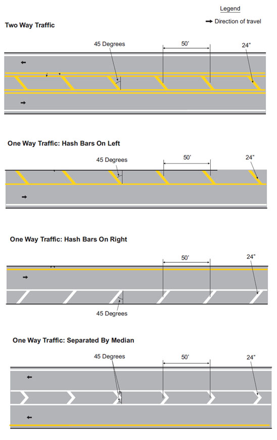
Option. Spaces required by the above may not need be provided in the particular lot. These spaces may be provided in a different location if they provide equivalent or greater accessibility for the disabled person (see Disabled Parking Areas).
Guidance. For disabled parking, depending upon the number of linear feet of curb requiring blue paint, 1 or 2 gallons of our standard white traffic paint should be taken to a local paint store to have blue paint pigment added. 10 ounces of the blue pigment should be added to 1 gallon of our standard white traffic paint. The blue paint pigment that can be used is available through Sherman Williams paint stores and other businesses that handle the "Blenda Color blue - No. A6011". The mixed blue paint will be lighter in color than the blue background we provide on our disabled parking signs, however, it will be acceptable.
Option. Blue lines may supplement white parking space markings of each parking space designated for use only by persons with disabilities.
Support. Additional parking space markings for the purpose of designating spaces for use only by persons with disabilities are discussed in EPG 620.2.20 and illustrated in International Symbol of Accessibility Parking Space Marking with Blue Background and White Border Options. The design and layout of accessible parking spaces for persons with disabilities is provided in the Americans with Disabilities Act Accessibility Guidelines for Buildings and Facilities (ADAAG) (see MUTCD Section 1A.11).
620.2.20 Pavement Word, Symbol and Arrow Markings (MUTCD Section 3B.20)
Guidance. Word, symbol and arrow markings on the pavement are used for the purpose of guiding, warning, or regulating traffic. These pavement markings can be helpful to road users in some locations by supplementing signs and providing additional emphasis for important regulatory, warning, or guidance messages, because the markings do not require diversion of the road user's attention from the roadway surface. Symbol messages are preferable to word messages. Examples of standard word and arrow pavement markings are shown in Standard Plan 620.00 and Fig. 620.2.20.7, Examples of Lane Reduction Arrow.
Option. Word, symbol and arrow markings, including those contained in the Standard Highway Signs and Markings book (see MUTCD Section 1A.11), may be used as determined by engineering judgment to supplement signs and/or to provide additional emphasis for regulatory, warning or guidance messages. Among the word, symbol and arrow markings that may be used are the following:
- A. Regulatory:
- 1. STOP
- 2. YIELD
- 3. RIGHT (LEFT) TURN ONLY
- 4. 25 MPH
- 5. Lane use and wrong way Arrow Symbols
- 6. Other preferential lane word markings
- B. Warning:
- 1. STOP AHEAD
- 2. YIELD AHEAD
- 3. YIELD AHEAD Triangle Symbol
- 4. SCHOOL XING
- 5. SIGNAL AHEAD
- 6. PED XING
- 7. SCHOOL
- 8. R X R
- 9. BUMP
- 10. HUMP
- 11. Lane reduction arrows
- C. Guide:
- 1. Route numbers (route shield pavement marking symbols and/or words such as I-70,US 40, STATE 135 or ROUTE 10)
- 2. Cardinal directions (NORTH, SOUTH, EAST or WEST)
- 3. TO
Standard. Word, symbol and arrow markings shall be white and reflectorized, except as otherwise provided in this article.
Pavement marking letters, numerals, symbols and arrows shall be installed in accordance with the design details in the Pavement Markings chapter of the Standard Highway Signs and Markings book (see MUTCD Section 1A.11).
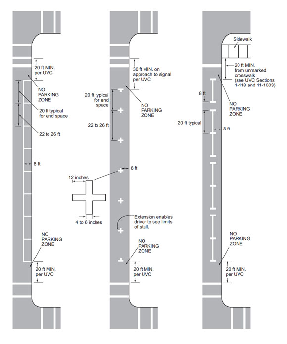
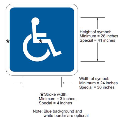

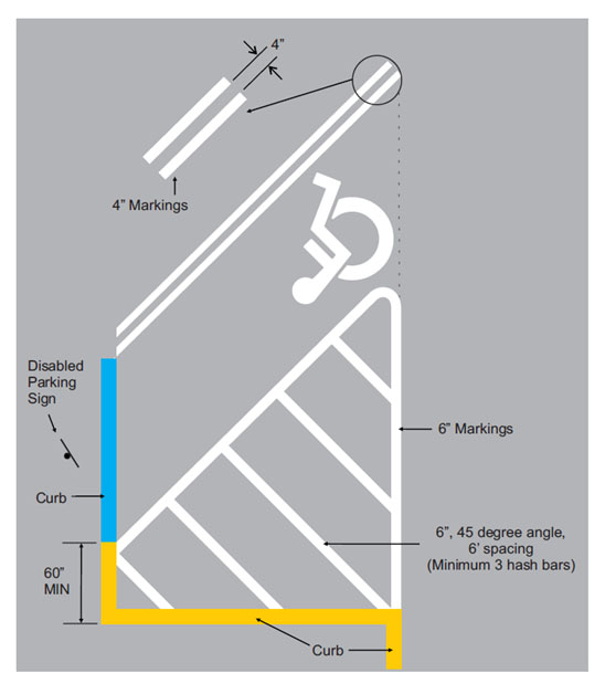
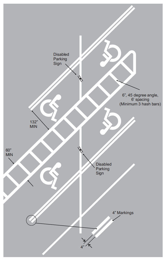
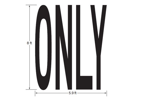
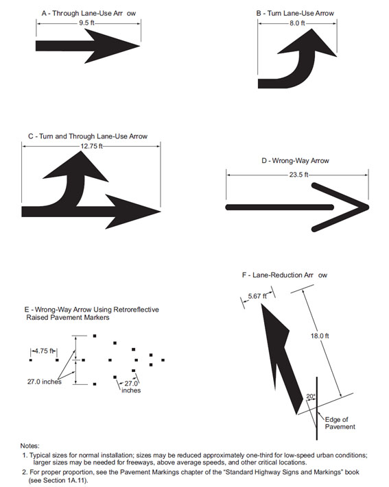
Guidance. When conveying mandatory messages, these markings should only be used as supplementary devices to the standard signs.
The elongation of these markings is dependent upon the posted speed limit and should be as follows:
| Table 620.2.20 Pavement Marking Lettering Heights and Spacings | ||
| Posted Speed Limit | Elongated Length | Approximate Space Between Word and Symbol |
|---|---|---|
| 35 mph or less | 8 ft. | 32 ft. |
| Greater than 35 mph | 10 ft. | 40 ft. |
The spacing between the word and symbol is approximate and should be adjusted as field conditions warrant.
Word and symbol markings should not exceed three lines of information.
If a pavement marking word message consists of more than one line of information, it should read in the direction of travel. The first word of the message should be nearest to the road user.
Except for the two opposing arrows of a two-way left-turn lane marking (see Fig. 620.2.2.2.4, Example of Two-Way, Left-Turn Marking Applications), the longitudinal space between word or symbol message markings, including arrow markings, should be at least four times the height of the characters for low-speed roads, but not more than ten times the height of the characters under any conditions.
The number of different word and symbol markings used should be minimized to provide effective guidance and avoid misunderstanding.
Except as noted below for the SCHOOL word marking (see MUTCD Section 7C.03) in the Option, pavement word, symbol and arrow markings should be no more than one lane in width.
Option. The SCHOOL word marking may extend to the width of two approach lanes (see Section 7C.03 in the MUTCD).
Guidance. When the SCHOOL word marking is extended to the width of two approach lanes, the characters should be 10 ft. or more tall (see Section 7C.03 in the MUTCD).
Pavement word, symbol and arrow markings should be proportionally scaled to fit within the width of the facility upon which they are applied.
Option. On narrow, low-speed shared-use paths, the pavement words, symbols nd arrows may be smaller than suggested, but to the relative scale.
Pavement markings simulating Interstate, U.S., State, and other official highway route shield signs (see MUTCD Figure 2D-3) with appropriate route numbers, but elongated for proper proportioning when viewed as a marking, may be used to guide road users to their destinations (see Figure 620.2.20.8, Examples of Elongated Route Shields for Pavement Markings).
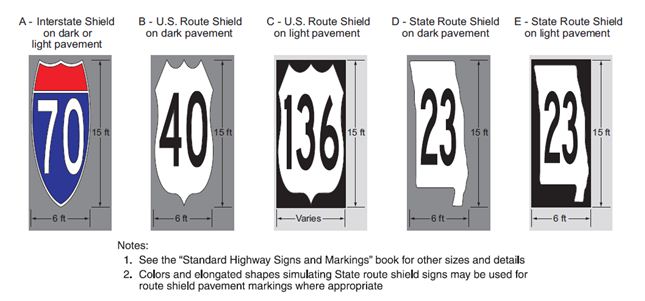
Standard. Except at the ends of aisles in parking lots, the word STOP shall not be used on the pavement unless accompanied by a stop line (see 620.2.16 Stop and Yield Lines (MUTCD Section 3B.16) and STOP (see MUTCD Section 2B.05) sign. At the ends of aisles in parking lots, the word STOP shall not be used on the pavement unless accompanied by a stop line.
The word STOP shall not be placed on the pavement in advance of a stop line, unless every vehicle is required to stop at all times.
Option. A yield-ahead triangle symbol (see Figure 620.2.20.10 Yield Ahead Triangle Symbols) or YIELD AHEAD word pavement marking may be used on approaches to intersections where the approaching traffic will encounter a YIELD sign at the intersection.
Standard. The yield-ahead triangle symbol or YIELD AHEAD word pavement marking shall not be used unless a YIELD sign is in place at the intersection. The yield-ahead symbol marking shall be as shown in Figure 620.2.20.10, Yield Ahead Triangle Symbols.
Guidance. The International Symbol of Accessibility parking space marking (see Fig. 620.2.20.2) should be placed in each parking space designated for use by persons with disabilities.
Option. A blue background with white border may supplement the wheelchair symbol as shown in Fig. 620.2.20.2 International Symbol of Accessibility Parking Space Marking with Blue Background and White Border Options.
Support. Lane-use arrow markings (see Fig. 620.2.20.7, Examples of Standard Arrows for Pavement Markings) are used to indicate the mandatory or permissible movements in certain lanes (see Fig. 620.2.22.2, Examples of Lane-Use Control Word and Arrow Pavement Markings) and in two-way left-turn lanes (see Fig. 620.2.2.2.4, Example of Two-Way Left-Turn Lane Marking Application).
Guidance. Lane-use arrow markings (see Fig. 620.2.20.7, Examples of Standard Arrows for Pavement Markings) should be used in lanes designated for the exclusive use of a turning movement, including turn bays, except where engineering judgment determines that physical conditions or other markings (such as a dotted extension of the lane line through the taper into the turn bay) clearly discourage unintentional use of a turn bay by through vehicles. Lane use arrows markings should also be used in lanes from which movements are allowed that are contrary to the normals rules of the road Figs. 620.2.8.1 and 620.3.8.2, Examples of Line Extensions through Intersections. When used in turn lanes, at least two arrows should be used, one at or near the upstream end of the full-width turn lane and one an appropriate distance upstream from the stop line or intersection Figs. 620.2.5.10.1 and 620.2.5.10.2, Examples of Applications of Conventional Road lane-Drop Marking and Fig. 620.2.20.9, Spacing of Arrows in Left Turn Lanes.
The placement of arrows in channelizing lanes should be determined by the length of the lane and the following criteria (see Fig. 620.2.20.9 Spacing of Arrows in Left Turn Lanes):
- A. The first arrow should be placed 75 ft. in advance of the stop bar.
- B. The second arrow should be placed 200 ft. in advance of the stop bar.
- C. Any additional arrows should be placed 400 ft. behind the stop bar.
Option. The distances between arrows may be adjusted if there are special circumstances that warrant the change.
Guidance. Where opposing offset channelized left-turn lanes exist, lane-use arrow markings should be placed near the downstream terminus of the offset left-turn lanes to reduce wrong-way movements (see MUTCD Fig. 2B-17).
Support. An arrow at the downstream end of a turn lane can help to prevent wrong way movements.
Standard. Where through lanes approaching an intersection become mandatory turn lanes, lane-use arrow markings shall be used and shall be accompanied by standard signs and the word ONLY.
The ONLY shall be placed on the pavement in advance of each arrow.
Lane use, lane reduction, and wrong-way arrow markings shall be designed as shown in Standard Plan 620.00 and Fig. 620.2.20.7, Examples of Standard Arrows for Pavement Markings.
Guidance. The use of straight arrows should be reserved for correcting special cases, such as, locations where accidents are occurring as a result of vehicles making turns from the through lanes.
Where through lanes become mandatory turn lanes, signs or markings should be repeated as necessary to prevent entrapment and to help the road user select the appropriate lane in advance of reaching a queue of waiting vehicles.
The word ONLY should be centered between all arrows used in the mandatory lane. Spacing between the arrow and the ONLY should be 4 to 10 times the height of the ONLY. In cases where the ONLY is set between two arrows it should be equally spaced between the arrows. The use of ONLY should not apply to exit ramps.
Option. On freeways or expressways where a through lane becomes a mandatory exit lane, lane-use arrow markings may be used on the approach to the exit in the dropped lane and in an adjacent optional through-or-exit lane if one exists.
Guidance. A two-way left-turn lane-use arrow pavement marking, with opposing arrows spaced as shown in Fig. 620.2.2.2.4 Example of Two-Way Left-Turn Lane Marking Application, should be used at or just downstream from the beginning of a two-way left-turn lane.
Option. Additional two-way left-turn lane-use arrow markings may be used at other locations along a two-way left-turn lane where engineering judgment determines that such additional markings are needed to emphasize the proper use of the lane.
Standard. A single-direction lane-use arrow shall not be used in a lane bordered on both sides by yellow two-way left-turn lane longitudinal markings.
Lane-use, lane-reduction, and wrong-way arrow markings shall be designed as shown in Fig. 620.2.20.7, Examples of Standard Arrows for Pavement Markings and in Standard Highway Signs and Markings (see MUTCD Section 1A.11).
Option. The ONLY word marking may be used to supplement the lane-use arrow markings in lanes that are designated for the exclusive use of a single movement (see Fig. 620.2.22.2, Examples of Lane-Use Control Word and Arrow Pavement Markings or to supplement a preferential lane word or symbol marking (see MUTCD Section 3D.01).
Standard. The ONLY word marking shall not be used in a lane that is shared by more than one movement.
Guidance. Where a lane-reduction transition occurs on a roadway with a speed limit of 45 mph or more, the lane-reduction arrow markings shown in "F" in Fig. 620.2.20.7, Examples of Standard Arrows for Pavement Markings should be used (see Fig. 620.2.9.1, Examples of Applications for Lane-Reduction Transition Marking). Except for acceleration lanes, where a lane-reduction transition occurs on a roadway with a speed limit of less than 45 mph, the lane-reduction arrow markings shown in "F" in Figure 620.2.20.7 should be used if determined to be appropriate based on engineering judgment. Examples of locations where they may be effective are at the terminus of hill climbing lanes, lane drops immediately after intersections, or other areas where the geometrics create a lane drop situation that is not obvious to the driver.
Option. Lane-reduction arrow markings may be used in long acceleration lanes based on engineering judgment.
Directional pavement arrows may be used as a substitute for the wrong-way arrows when wrong-way arrows are required.
A maximum of two wrong-way arrows may be provided on a ramp, the placement of the second arrow is dependent upon the design and length of the ramp. Exit ramps that do not contain islands at the intersection of the exit ramp and the crossroad may receive one wrong-way pavement arrow at the top of the ramp. Ramps constructed with islands at the intersection of the exit ramp and the crossroad may receive two wrong-way arrows at the top of the ramp, one arrow on each side of the island.
Wrong-way pavement arrows may be placed on one way outer roads to further indicate the proper direction to travel.
Standard. In the case of two lane ramps where wrong-way pavement arrows are used, one arrow shall be provided for each lane.
Guidance. If used, the point of the wrong-way arrow should be located a distance of 25 ft. from the end of the ramp and the intersecting crossroad. When wrong-way arrows are used on one-way outer roads, the arrows should be installed 25 ft. in advance of the point where the edge of the crossroad and the outer road meet. Where a stop bar has been provided, the arrow should be placed 25 ft. in advance of this marking.
On ramps where directional pavement arrows have been provided to aid the motorist in proper lane usage, the wrong-way pavement arrows should not be used.
Where crossroad channelization or ramp geometrics do not make wrong-way movements difficult, the appropriate lane-use arrow should be placed in each lane of an exit ramp near the crossroad terminal where it will be clearly visible to a potential wrong-way road user.
Option. The wrong-way arrow markings shown in "D" in Fig. 620.2.20.7, Examples of Standard Arrows for Pavement Markings may be placed near the downstream terminus of a ramp as shown in Examples of Arrow Markings at Exit Ramp Terminals (MUTCD Figs. 2B-18 and -19) or at other locations where lane-use arrows are not appropriate, to indicate the correct direction of traffic flow and to discourage drivers from traveling in the wrong direction.
A yield-ahead triangle symbol or YIELD AHEAD word pavement marking may be used on approaches to intersections where the approaching traffic will encounter a YIELD sign at the intersection (see Yield Ahead Triangle Symbols).
Support. Lane-use arrow markings are often used to provide guidance in turn bays, where turns may or may not be mandatory, and in two-way left-turn lanes.
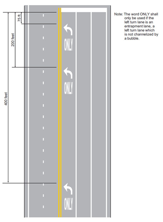
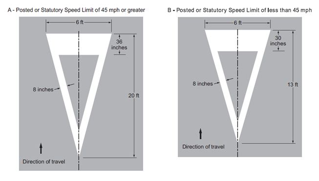
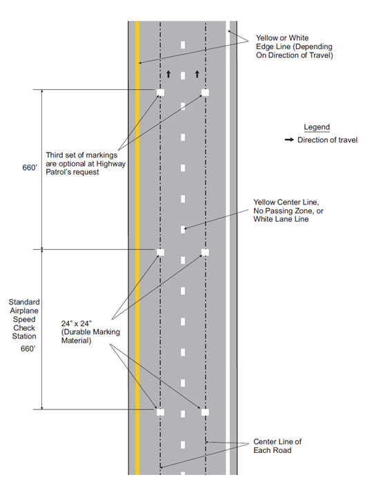
620.2.21 Aircraft Speed Measurement Markings (MUTCD Section 3B.21)
Support. An aircraft speed measurement marking is a transverse marking placed on the roadway to assist the enforcement of speed regulations.
Standard. Aircraft speed check markings shall only be installed after the District Engineer or his/her representative receives a request from the Missouri State Highway Patrol. A member of the Highway Patrol shall be present when these stations are placed to verify their location and spacing for legal purposes.
Speed measurement markings, if used, shall be white, and shall be 24 in. x 24 in. and he distance between the block shall be 660 ft., measured from the leading edge of the first block to the leading edge of the second block. This distance shall be measured on the actual pavement surface and is the same for all posted speeds (See Fig. 620.2.20.11, Pavement Marking for Aircraft Speed Check Stations).
The markings shall be reflective, and are to be placed on the center of each driving lane.
Those markings, which have been improperly installed shall be removed by one of the methods noted in Obliteration of Pavement Markings.
Option. A third block may be installed at the special request of the Highway Patrol.
If the Highway Patrol wishes to only check traffic flowing in one direction, these markings may be omitted from the opposing lanes.
Guidance. Aircraft speed check markings should receive periodic inspection to ensure they are maintained in an acceptable and functional manner. Existing aircraft speed check markings that are no longer in use should be allowed to deteriorate.
The application of any material should be done following the manufacturer’s recommendations for installation.
Option. On concrete surfaces, black may be used to provide contrast of the speed blocks.
620.2.22 Speed Reduction Markings (MUTCD Section 3B.22)
Support. Speed reduction markings (see Fig. 620.2.22.1, Example of the Application of speed Reduction Markings) are transverse markings that are placed on the roadway within a lane (along both edges of the lane) in a pattern of progressively reduced spacing to give drivers the impression that their speed is increasing. These markings might be placed in advance of an unexpectedly severe horizontal or vertical curve or other roadway feature where drivers need to decelerate prior to reaching the feature and where the desired reduction in speeds has not been achieved by the installation of warning signs and/or other traffic control devices.
Guidance. If used, speed reduction markings should be reserved for unexpected curves and should not be used on long tangent sections of roadway or in areas frequented mainly by local or familiar drivers, (e.g., school zones). If used, speed reduction markings should supplement the appropriate warning signs and other traffic control devices and should not substitute for these devices.
Standard. If used, speed reduction markings shall be a series of white transverse lines on both sides of the lane that are perpendicular to the centerline, edgeline or lane line. The longitudinal spacing between the markings shall be progressively reduced from the upstream to the downstream end of the marked portion of the lane.
Guidance. Speed reduction markings should not be greater than 12 in. wide and should not extend more than 18 in. into the lane.
Standard. Speed reduction markings shall not be used in lanes that do not have a longitudinal line (centerline, edgeline or lane line) on both sides of the lane.
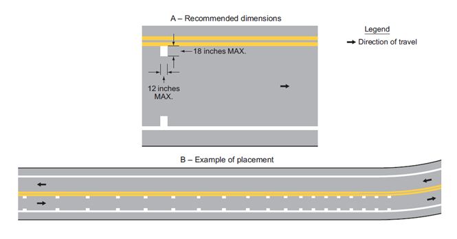

620.2.23 Curb Markings (MUTCD Section 3B.23)
Support. Curb markings are most often used to indicate parking regulations or to delineate the curb.
Standard. Where curbs are marked to convey parking regulations in those areas where curb markings are frequently obscured by snow and ice accumulation signs shall be used with the curb markings except as provided below.
All barrier curbs, curbs a minimum of 6 in. tall with a vertical face shall be marked.
Guidance. Except as provided in the Option, when curb markings are used without signs to convey parking regulations, a legible word marking regarding the regulation (such as “No Parking” or “No Standing”) should be placed on the curb.
Option. Curb markings without word markings or signs may be used to convey a general prohibition by statute of parking within a specified distance of a STOP sign, YIELD sign, driveway, fire hydrant or crosswalk.
Local highway agencies may prescribe special colors for curb markings to supplement standard signs for parking regulation.
Support. Since yellow and white curb markings are frequently used for curb delineation and visibility, it is advisable to establish parking regulations through the installation of standard signs (see EPG 903.5.35 Parking, Standing and Stopping Signs (R7 and R8 Series) (MUTCD Section 2B.39) through EPG 903.5.37 RESERVED PARKING For Persons with Disabilities Sign (R7-8, R7-8b) (MUTCD Section 2B.41b)).
Standard. Where curbs are marked for delineation or visibility purposes, the colors shall comply with to the general principles of markings (see EPG 620.1.5 Colors (MUTCD Section 3A.05).
Guidance. Curbs should not be marked in the following cases:
- A. Where the posted speed limit is 40 mph or less,
- B. Curbs that diverge from the normal traffic flow for commercial and private entrances,
- C. Curbs that are mountable (less than 6 in. tall).
Standard. Barrier curbs shall be marked in cases A to C if they are used to redirect the flow of traffic.
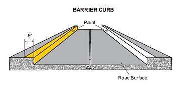
Option. The first 200 ft. of a barrier curb may also be painted in the above cases to mark the beginning of these barriers (See Fig. 620.2.23, Typical Markings for Barrier Curb).
Guidance. Retroreflective solid yellow markings should be placed on approach ends of raised medians and curbs of islands that are located in the line of traffic flow where the curb serves to channel traffic to the right of the obstruction.
Retroreflective solid white markings should be used when traffic is permitted pass on either side of the island.
Support. Where the curbs of the islands become parallel to the direction of traffic flow, it is not necessary to mark the curbs unless an engineering study indicates the need for this type of delineation.
Curbs at openings in a continuous median island need not be marked unless an engineering study indicates the need for this type of marking.
Option. Retroreflective or internally illuminated raised pavement markers of the appropriate color may be placed on the pavement in front of the curb and/or on the top of curbed noses of raised medians and curbs of islands, as a supplement to or substitute for retroreflective curb markings used for delineation.
620.2.24 Chevrons and Diagonal Crosshatch (Hash Bar) markings (MUTCD Section 3B.24)
Guidance. Hash bars may be used to supplement other pavement marking which delineate locations not to be driven on. Examples of such markings are:
- A. Left turn bubbles,
- B. No Parking areas,
- C. Gore Points,
- D. Shoulders,
- E. Pavement Transitions and
- F. Painted Medians.
If there is insufficient space to place a minimum of 3 hash bars at 50 ft. intervals, the spacing should be reduced (See Fig. 620.2.19 Typical Hash Bar Markings).
Option. Chevron and diagonal crosshatch markings may be used to discourage travel on certain paved areas, such as shoulders, gore areas, flush median areas between solid double yellow centerline markings or between white channelizing lines approaching obstructions in the roadway (see EPG 620.2.10 Approach Markings for Obstructions (MUTCD Section 3B.10) and Figs. 620.2.10.2 and 620.2.10.3, Examples of Applications of Markings for Obstructions in the Roadway), between solid double yellow centerline markings forming flush medians or channelized travel paths at intersections (see Fig. 620.2.2.0.2, Examples of Four-or-More Lane, Two-Way marking Applications and Fig. 620.2.2.2.2, Example of Application of Three-lane, Two-Way Makings for Changing Direction of the Center Lane), buffer spaces between preferential lanes and general-purpose lanes (see Figs. 620.4.2.2 Markings for Buffer-Separated Preferential Lanes (MUTCD 3D-2) and Fig. 620.4.2.5 Markings for Counter-Flow Preferential Lanes on Divided Highways (MUTCD 3D-4)), and at grade crossings (see MUTCD Part 8).
Standard. Hash bars shall be marked using a 24 in. wide stripe set at a 45 degree angle to the driving lane.
The standard spacing between hash bars shall be 50 ft. with a minimum of 3 hash bars being used per application.
When crosshatch markings are used in paved areas that separate traffic flows in the same general direction, they shall be white and they shall be shaped as chevron markings, with the point of each chevron facing toward approaching traffic, as shown in Figs. 620.2.5.1 and 620.2.5.2, Examples of Dotted Line and Channelizing Line Application for Exit Ramp Markings, "A" of Fig. 620.2.5.3, Examples of Dotted Line and Channelizing Line Application for Entrance Ramp Markings, Figs. 620.2.5.5 through 620.2.5.9, Examples of Applications of Freeway and Expressway Lane-Drop Markings and Fig. 620.2.10.3, Examples of Applications of Markings for Obstructions in the Roadway.
When crosshatch markings are used in paved areas that separate opposing directions of traffic, they shall be yellow diagonal markings that slant away from traffic in the adjacent travel lanes, as shown in Fig. 620.2.2.0.2, Examples of Four-or-More Lane, Two-Way marking Applications and Fig. 620.2.2.2.2, Example of Application of Three-lane, Two-Way Makings for Changing Direction of the Center Lane and Both "A" and "B" of Fig. 620.2.10.2, Examples of Applications of Markings for Obstructions in the Roadway.
When crosshatch markings are used on paved shoulders, they shall be diagonal markings that slant away from traffic in the adjacent travel lane. The diagonal markings shall be yellow when used on the left-hand shoulders of the roadways of divided highways and on the left-hand shoulders of one-way streets or ramps. The diagonal markings shall be white when used on right-hand shoulders.
620.2.25 Speed Hump Markings (MUTCD Section 3B.25)
Standard. If speed hump markings are used, they shall be a series of white markings placed on a speed hump to identify its location. If markings are used for a speed hump that does not also function as a crosswalk or speed table, the markings shall comply with Option A, B or C shown in Fig. 620.2.26.1, Pavement Markings for Speed Humps without Crosswalks. If markings are used for a speed hump that also functions as a crosswalk or speed table, the markings shall comply with Option A or B shown in Figure 620.2.26.2, Pavement Markings for Speed Tables or Speed Humps with Crosswalks.
620.2.26 Advance Speed Hump Markings (MUTCD Section 3B.26)
Option. Advance speed hump markings (see Fig. 620.2.26.3, Advance Warning Markings for Speed Humps) may be used in advance of speed humps or other engineered vertical roadway deflections such as dips where added visibility is desired or where such deflection is not expected.
Advance pavement wording such as BUMP or HUMP (see EPG 620.2.20) may be used on the approach to a speed hump either alone or in conjunction with advance speed hump markings. Appropriate advance warning signs may be used in compliance with MUTCD Section 2C.29.
Standard. If advance speed hump markings are used, they shall be a series of eight white 12 in. transverse lines that become longer and are spaced closer together as the vehicle approaches the speed humps or other deflection. If advance markings are used, they shall comply with the detailed design shown in Fig. 620.2.26.3, Advance Warning Markings for Speed Humps.
Guidance. If used, advance speed hump markings should be installed in each approach lane.
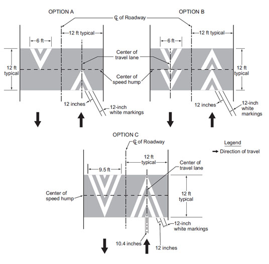
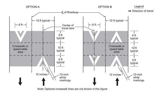
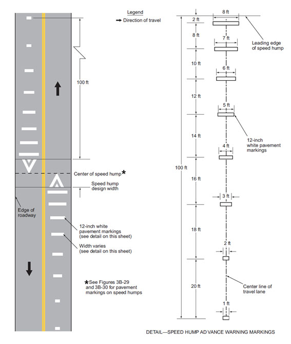
620.2.27 Pavement Markings for Highway-Rail Grade Crossings (MUTCD Section 8B.27)
Standard. All grade crossing pavement markings shall be retroreflectorized white. All other markings shall be in accordance with EPG 620 Pavement Marking.
On paved roadways, pavement markings in advance of a grade crossing shall consist of an X, the letters RR, a no-passing zone marking (on two-lane, two-way highways with centerline markings in compliance with EPG 620.2.1), and certain transverse lines as shown in Fig. 620.2.28.1, Example of Placement of Warning Signs and Pavement Markings at Grade Crossings and Fig. 620.2.28.2, Grade Crossing Pavement Markings.
Identical markings shall be placed in each approach lane on all paved approaches to grade crossings where signals or automatic gates are located, and at all other grade crossings where the posted or statutory highway speed is 40 mph or greater.
Pavement markings shall not be required at grade crossings where the posted or statutory highway speed is less than 40 mph if an engineering study indicates that other installed devices provide suitable warning and control. Pavement markings shall not be required at grade crossings in urban areas if an engineering study indicates that other installed devices provide suitable warning and control.
Guidance. When pavement markings are used, a portion of the X symbol should be directly opposite the Grade Crossing Advance Warning sign. The X symbol and letters should be elongated to allow for the low angle at which they will be viewed.
Option. When justified by engineering judgment, supplemental pavement marking symbol(s) may be placed between the Grade Crossing Advance Warning sign and the grade crossing.
620.2.28 Stop and Yield Lines at Highway-Rail Grade Crossings (MUTCD section 8B.28)
Standard. On paved roadways at grade crossings that are equipped with active control devices such as flashing-light signals, gates, or traffic control signals, a stop line (see EPG 620.2.16) shall be installed to indicate the point behind which highway vehicles are or might be required to stop.
Guidance. On paved roadway approaches to passive grade crossings where a STOP sign is installed in conjunction with the Crossbuck sign, a stop line should be installed to indicate the point behind which highway vehicles are required to stop or as near to that point as practical.
If a stop line is used, it should be a transverse line at a right angle to the traveled way and should be placed approximately 8 ft. in advance of the gate (if present), but no closer than 15 ft. in advance of the nearest rail.
Option. On paved roadway approaches to passive grade crossings where a YIELD sign is installed in conjunction with the Crossbuck sign, a yield line (see EPG 620.2.16) or a stop line may be installed to indicate the point behind which highway vehicles are required to yield or stop or as near to that point as practical.
Guidance. If a yield line is used, it should be a transverse line (see Fig. 620.2.16, Examples of Yield Line Layouts) at a right angle to the traveled way and should be placed no closer than 15 ft. in advance of the nearest rail (see Fig. 620.2.28.2, Grade Crossing Pavement Markings).
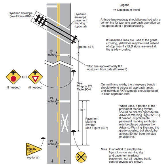
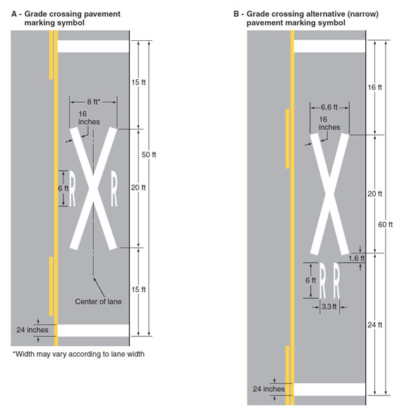
620.2.29 Pavement Markings for Bicycle Facilities (MUTCD Section 9C)
620.2.29.1 Functions of Markings (MUTCD Section 9C.01)
Support. Markings indicate the separation of the lanes for road users, assist the bicyclist by indicating assigned travel paths, indicate correct position for traffic control signal actuation and provide advance information for turning and crossing maneuvers.
620.2.29.2 General Principles (MUTCD Section 9C.03)
Guidance. Bikeway design guides (see MUTCD Section 9A.05) should be used when designing markings for bicycle facilities.
Standard. Markings used on bikeways shall be retroreflectorized.
Guidance. Pavement marking word messages, symbols, and/or arrows should be used in bikeways where appropriate. Consideration should be given to selecting pavement marking materials that will minimize loss of traction for bicycles under wet conditions.
Standard. The colors, width of lines, patterns of lines, symbols, and arrows used for marking bicycle facilities shall be as defined in EPG 620.1.5, EPG 620.1.6 and EPG 620.2.20.
Support. All the figures in EPG 620.2.29 show examples of the application of lines, word messages, symbols and arrows on designated bikeways.
Option. A dotted line may be used to define a specific path for a bicyclist crossing an intersection (see Figure 620.2.29.4.1) as described in EPG 620.1.6 and EPG 620.2.8.
Option. Where shared-use paths are of sufficient width to designate two minimum width lanes, a solid yellow line may be used to separate the two directions of travel where passing is not permitted, and a broken yellow line may be used where passing is permitted (see Fig. 620.2.29.4.2).
Guidance. Broken lines used on shared-use paths should have the usual 1-to-3 segment-to-gap ratio. A nominal 3 ft. segment with a 9 ft. gap should be used.
If conditions make it desirable to separate two directions of travel on shared-use paths at particular locations, a solid yellow line should be used to indicate no passing and no traveling to the left of the line.
Markings as shown in Fig 620.2.29.4.2 should be used at the location of obstructions in the center of the path, including vertical elements intended to physically prevent unauthorized motor vehicles from entering the path.
Option. A solid white line may be used on shared-use paths to separate different types of users. The R9-7 sign (see MUTCD Section 9B.12) may be used to supplement the solid white line.
Smaller size letters and symbols may be used on shared-use paths. Where arrows are needed on shared-use paths, half-size layouts of the arrows may be used (see EPG 620.2.20).
620.2.29.4 Markings for Bicycle Lanes (MUTCD Section 9C.04)
Support. Pavement markings designate that portion of the roadway for preferential use by bicyclists. Markings inform all road users of the restricted nature of the bicycle lane.
Standard. Longitudinal pavement markings shall be used to define bicycle lanes.
Guidance. If used, bicycle lane word, symbol, and/or arrow markings (see Figure 620.2.29.4.3) should be placed at the beginning of a bicycle lane and at periodic intervals along the bicycle lane based on engineering judgment.
Standard. If the bicycle lane symbol marking is used in conjunction with word or arrow messages, it shall precede them.
Option. If the word, symbol, and/or arrow pavement markings shown in Figure 620.2.29.4.3 are used, Bike Lane signs (see MUTCD Section 9B.04) may also be used, but to avoid overuse of the signs not necessarily adjacent to every set of pavement markings.
Standard. A through bicycle lane shall not be positioned to the right of a right turn only lane or to the left of a left turn only lane.
Support. A bicyclist continuing straight through an intersection from the right of a right-turn lane or from the left of a left-turn lane would be inconsistent with normal traffic behavior and would violate the expectations of right- or left-turning motorists.
Guidance. When the right through lane is dropped to become a right turn only lane, the bicycle lane markings should stop at least 100 ft. before the beginning of the right-turn lane. Through bicycle lane markings should resume to the left of the right turn only lane.
An optional through-right turn lane next to a right turn only lane should not be used where there is a through bicycle lane. If a capacity analysis indicates the need for an optional through-right turn lane, the bicycle lane should be discontinued at the intersection approach.
Posts or raised pavement markers should not be used to separate bicycle lanes from adjacent travel lanes.
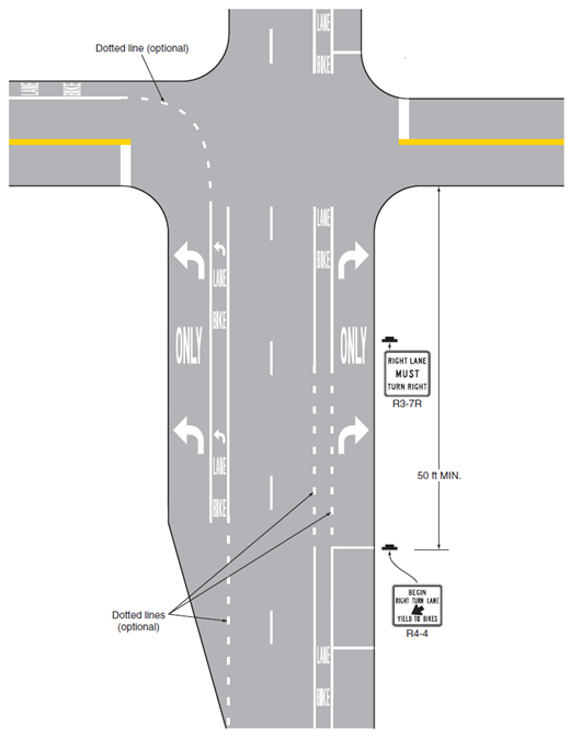
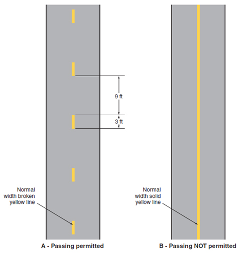
Support. Using raised devices creates a collision potential for bicyclists by placing fixed objects immediately adjacent to the travel path of the bicyclist. In addition, raised devices can prevent vehicles turning right from merging with the bicycle lane, which is the preferred method for making the right turn. Raised devices used to define a bicycle lane can also cause problems in cleaning and maintaining the bicycle lane.
Standard. Bicycle lanes shall not be provided on the circular roadway of a roundabout.
Guidance. Bicycle lane markings should stop at least 100 ft. before the crosswalk, or if no crosswalk is provided, at least 100 ft. before the yield line, or if no yield line is provided, then at least 100 ft. before the edge of the circulatory roadway.
Support. Examples of bicycle lane markings at right-turn lanes are shown in Figures 620.2.29.4.1, 620.2.29.7.1 and 620.2.29.7.2. Examples of pavement markings for bicycle lanes on a two-way street are shown in Figure 620.2.29.7.3. Pavement word message, symbol and arrow markings for bicycle lanes are shown in Figure 620.2.29.4.3.
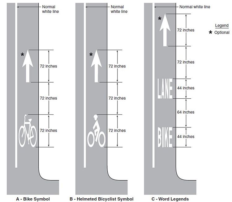
620.2.29.5 Bicycle Detector Symbol (MUTCD Section 9C.05)
Option. A symbol (see Fig. 620.2.29.7.4) may be placed on the pavement indicating the optimum position for a bicyclist to actuate the signal.
An R10-22 sign (see MUTCD Section 9B.13 and MUTCD Figure 9B-2) may be installed to supplement the pavement marking.
620.2.29.6 Pavement Markings for Obstructions (MUTCD Section 9C.06)
Guidance. In roadway situations where it is not practical to eliminate a drain grate or other roadway obstruction that is inappropriate for bicycle travel, white markings applied as shown in Figure 620.2.29.7.5 should be used to guide bicyclists around the condition.
Option. The Shared Lane Marking shown in Fig. 620.2.29.7.6 may be used to:
A. Assist bicyclists with lateral positioning in a shared lane with on-street parallel parking in order to reduce the chance of a bicyclist’s impacting the open door of a parked vehicle,
B. Assist bicyclists with lateral positioning in lanes that are too narrow for a motor vehicle and a bicycle to travel side by side within the same traffic lane,
C. Alert road users of the lateral location bicyclists are likely to occupy within the traveled way,
D. Encourage safe passing of bicyclists by motorists, and
E. Reduce the incidence of wrong-way bicycling.
Guidance. The Shared Lane Marking should not be placed on roadways that have a speed limit above 35 mph.
Standard. Shared Lane Markings shall not be used on shoulders or in designated bicycle lanes.
Guidance. If used in a shared lane with on-street parallel parking, Shared Lane Markings should be placed so that the centers of the markings are at least 11 ft. from the face of the curb, or from the edge of the pavement where there is no curb.
If used on a street without on-street parking that has an outside travel lane that is narrower than 14 ft., the centers of the Shared Lane Markings should be at least 4 ft. from the face of the curb, or from the edge of the pavement where there is no curb.
If used, the Shared Lane Marking should be placed immediately after an intersection and spaced at intervals not greater than 250 ft. thereafter.
Option. MUTCD Section 9B.06 describes a Bicycles May Use Full Lane sign that may be used in addition to or instead of the Shared Lane Marking to inform road users that bicyclists might occupy the travel lane.

