237.1 Plan Details

The details required on plans are further discussed throughout the Engineering Policy Guidelines. The designer is to refer to the standard specifications for more information on individual items.
237.1.1 Plan Preparation
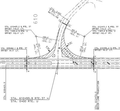
A set of detail plans normally consists of the following sheets: (1) title sheet, (2) typical section sheet(s), (3) summary of quantities 2B sheet(s), (4) plan-profile sheets, (5) referenced point sheet, (6) coordinate points sheet, (7) special sheets, including traffic control, temporary erosion and sediment control, lighting, signals, or signing plans, (8) culvert section sheets, (9) bridge plan sheets, (10) standard plans and (11) computer sheets or cross-section sheets. An example of a set of plans is shown in Sample Plans. These examples are intended to illustrate certain features and are not intended to show complete details.
All sheets for plans are electronically submitted via the ProjectWise document management system in PDF format generated as a D-size (22 in. x 34 in.). Drawings need to be centered on the page, so that no part of the drawing is cut off during reproduction. Shading, dense hatching, aerial photographs, pictures and line weights less than 1 are not allowed because those areas will not copy adequately. The district identifies all sheets by the job number.
| Additional Information |
| Relocation of Service Signs (Supplemental Guide Sign Program Signs) on Construction Projects |
Plans are to be neat and prepared to the precision requirements outlined in Table 237.1.1. Plans shall be developed in accordance with Specifications of Computer Deliverable Contract Plans. CADD Standards are to be adhered to when preparing plans. This manual is a visual reference to the settings managers used by MoDOT, showing lettering styles and sizes and common symbols used in plan production.
A consultant’s logo shall be placed on all plan sheets produced for MoDOT improvement projects. The logo will not be larger than 2 in. in height or width (as measured on a standard size sheet as specified above) and will be located immediately above, below, or adjacent to the title block.
Data covered in the standard specifications are not to be repeated on the plans. References to the standard specifications are discouraged. References on the plans to standard plans are also discouraged, except as required to identify the proper drawing where more than one standard may be used for a construction item such as box culverts and drop inlets. In these cases, the reference to the standard plans is made on the 2B sheet, rather than in the notes on the plans.
Precision. Plans, plan quantities and plan dimensions are developed on the basis of precision and to significant figures consistent with the basic data on which they are developed and consistent with the unit of measurement and basis of payment for the items being considered. It is useless to compute angles, curve lengths, etc. for interchange geometrics to 0.001 ft. and 0 degrees 00 minutes 01 seconds accuracy when the survey data, on which the calculations are based, are measured to the nearest 0.01 ft. and 0 degrees 00 minutes 6 seconds. Another example is that detail drafting and calculations for a precise length of box culvert are not necessary because the end lengths of box culverts are measured, and quantities are computed, on the basis of a length to the nearest foot. Precision for dimensions used in the preparation of plans is shown in Table 237.1.1. The precision for other items is consistent with the figures given. Where computed items are rounded to the specified precision or quantity, half increments, or more, are rounded to the next higher unit. Less than half increments are rounded to the next lower unit.
Table 237.1.1 Precision for Plan Dimensions
| Dimension | English Precision |
|---|---|
| All Stationing | |
| 0.01 ft. | |
| Topography | |
| Stationing | 1.0 ft. |
| Offset | 1.0 ft. |
| Angle | 0 degrees 01 minutes |
| Bearings & Angles | |
| 0 degrees 00 minutes 1 second | |
| Right of way | |
| Stationing | 0.1 ft. (1.0 ft. or 5.0 ft. preferable) |
| Width | 1.0 ft. (5.0 ft. preferable) |
| Area | |
| 0.01 acre or 1.0 ft2 | |
| Referenced Points | |
| Stationing | 0.01 ft. |
| Ties | 0.1 ft. |
| Bench Marks | |
| Stationing | 1.0 ft. |
| Offset | 1.0 ft. |
| Elevation | 0.01 ft. |
| Profile Grade | |
| P.I. station | 0.01 ft. |
| P.I. elevation | 0.01 ft. |
| Rate of grade | 0.001% (Where practical) |
| Length of vertical curve | |
| 10 ft. increments | |
| Stopping sight distance | |
| 5.0 ft. | |
| K" factors | |
| Nearest whole number | |
| Flow line elevation | |
| 0.1 ft. | |
| Items to be constructed | |
| Stationing | 0.1 ft. (1.0 ft. preferable) |
| Culvert Lengths | |
| 1.0 ft. (or next even ft. for metal pipe culverts) | |
237.1.2 Project Limits
Project limits are set to define major work limits that are usually the limits of surfacing for the main roadway, excluding connections. Project limits usually begin at the first full typical section and minimum right of way; incidental work such as the construction of bypasses and temporary connections, and sometimes grading, may extend beyond project limits. If separate contracts are awarded within the limits of any one project, the design plans are to delineate the area of interfacing with any other contracts.

Federal requirements specify that stub-end routes on the supplementary system must end at a local traffic generating point. A local traffic generating point is defined as a town or village, school, church, cemetery, cluster of farm buildings, state parks or a county road intersection. All projects must have logical termini, as described in Logical Termini, including level course, pavement marking, etc.