Unused files
Jump to navigation
Jump to search
The following files exist but are not embedded in any page. Please note that other websites may link to a file with a direct URL, and so may still be listed here despite being in active use.
Showing below up to 50 results in range #3,051 to #3,100.
-
 620.15.14.1 Sheet 5.jpg 629 × 871; 194 KB
-
 620.15.14.1 Sheet 6.jpg 628 × 857; 185 KB
-
 620.15.14.1 Sheet 7.jpg 636 × 648; 102 KB
-
 620.15.14.2.jpg 635 × 652; 115 KB
-

-
-
-
-
-
 Main Page Jan 20, 2012.jpg 820 × 601; 124 KB
-
 Main Page 4 Jan 25, 2012.jpg 1,049 × 714; 125 KB
-
-
 Main Page 2 Feb 7, 2012.jpg 743 × 373; 51 KB
-
 Main Page Feb 7, 2012.jpg 574 × 655; 55 KB
-
 Main Page 3 Feb 7, 2012.jpg 656 × 399; 45 KB
-
 643.4.4.2.jpg 1,161 × 817; 103 KB
-
 236.16.2 Outdoor Advertising Area Map Feb 2012.jpg 1,242 × 954; 165 KB
-
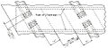
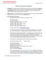
 751.22 Open Int Bent Diaphragms Dim Part Elevations.jpg 1,084 × 485; 80 KB
-
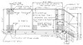
 751.22 Open Int Bent Diaphragms Dim Part Plan.jpg 493 × 221; 53 KB
-
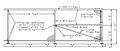
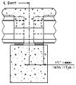 751.22 Open Int Bent Diaphragms Dim Part Section.jpg 232 × 257; 37 KB
-

-

-

-

-

-

-

-

-
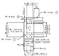
 751.35 wide flange and plate girders-part section near end bent.jpg 658 × 450; 93 KB
-
 751.35 wide flange and plate girders-section a-a.jpg 377 × 364; 42 KB
-
 751.35 wide flange and plate girders-section b-b.jpg 271 × 266; 31 KB
-
 751.35 wide flange and plate girders-section c-c.jpg 288 × 285; 32 KB
-
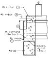
 751.35 prestressed girders-section a-a.jpg 350 × 329; 42 KB
-
 751.35 prestressed girders-section b-b.jpg 253 × 234; 30 KB
-
 751.35 prestressed girders-section c-c.jpg 234 × 284; 33 KB
-
 751.35 prestressed girders-section d-d.jpg 262 × 250; 29 KB
-
 751.11.3.6 front elevation.jpg 423 × 303; 53 KB
-
 751.11.3.6 side.jpg 592 × 261; 41 KB
-
 Main Page 2 Feb 14, 2012.jpg 1,131 × 552; 90 KB
-
 402 Contract Leveling Course Guidelines Feb 17, 2012.doc 1,275 × 1,650, 4 pages; 34 KB
-
 409 Contract Seal Coat Guidelines Feb 17, 2012.doc 1,275 × 1,650, 4 pages; 183 KB
-
409 JSP Feb 17, 2012.doc ; 81 KB
-
 136 google lpa.jpg 226 × 116; 14 KB
-
Fig. 104.13.ppt ; 241 KB
-
 751.12.4 superstructure near steps.jpg 799 × 430; 71 KB
-
 751.12.4 superstructure near end panel.jpg 786 × 333; 43 KB
-
 751.12.4 handrail bracket.jpg 797 × 502; 40 KB
-
 751.12.4 rail post connection.jpg 794 × 542; 51 KB
-
 751.12.4 plan of floor plate.jpg 782 × 532; 40 KB
-
 751.12.4 details of expansion device gap.jpg 787 × 460; 66 KB


