Uncategorized files
Jump to navigation
Jump to search
Showing below up to 50 results in range #5,951 to #6,000.
-
 750.1 Trapezoidal Channel 7 ft.pdf 1,275 × 1,650; 16 KB
-
 750.1 Trapezoidal Channel 8 ft.pdf 1,275 × 1,650; 16 KB
-
 750.1 Trapezoidal Channel 8 ft 6to1 2to1.pdf 1,275 × 1,650; 16 KB
-
 750.1 Trapezoidal Channel 8 ft 6to1 3to1.pdf 1,275 × 1,650; 15 KB
-
 750.1 Trapezoidal Channel 9 ft.pdf 1,275 × 1,650; 16 KB
-
 750.1 Triangular Channel 3to1 2to1.pdf 1,275 × 1,650; 15 KB
-
 750.1 Triangular Channel 4to1 2to1.pdf 1,275 × 1,650; 15 KB
-
 750.1 Triangular Channel 4to1 3to1.pdf 1,275 × 1,650; 15 KB
-
 750.1 Triangular Channel 4to1 4to1.pdf 1,275 × 1,650; 15 KB
-
 750.1 Triangular Channel 6to1 2to1.pdf 1,275 × 1,650; 15 KB
-
 750.1 Triangular Channel 6to1 3to1.pdf 1,275 × 1,650; 15 KB
-
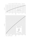 750.2 Critical Depth for Box Culverts.pdf 1,477 × 1,256, 2 pages; 34 KB
-
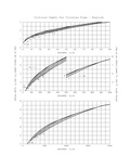
 750.2 Critical Depth for CMP Arch.pdf 1,450 × 1,272, 2 pages; 43 KB
-
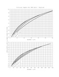
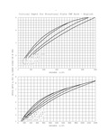
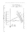
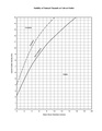
 750.2 Critical Depth for Circular Pipe.pdf 1,470 × 1,260, 2 pages; 54 KB
-
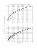 750.2 Critical Depth for Elliptical Concrete Pipe.pdf 1,487 × 1,262, 2 pages; 45 KB
-
 750.2 Critical Depth for Structural Plate CMP Arch.pdf 1,450 × 1,272, 2 pages; 45 KB
-
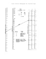
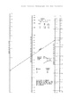 750.2 Inlet Control Nomograph for Box Culverts.pdf 1,275 × 1,650; 29 KB
-
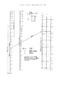 750.2 Inlet Control Nomograph for CMP.pdf 1,275 × 1,650; 34 KB
-
 750.2 Inlet Control Nomograph for CMP Arch.pdf 1,275 × 1,650; 37 KB
-
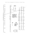
 750.2 Inlet Control Nomograph for Concrete Pipe.pdf 1,275 × 1,650; 31 KB
-
 750.2 Inlet Control Nomograph for Elliptical Concrete Pipe.pdf 1,275 × 1,650; 33 KB
-
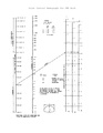
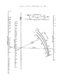 750.2 Outlet Control Nomograph for CMP.pdf 1,275 × 1,650; 30 KB
-
 750.2 Outlet Control Nomograph for CMP Arch.pdf 1,275 × 1,650; 30 KB
-
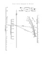
 750.2 Outlet Control Nomograph for Concrete Pipe.pdf 1,275 × 1,650; 29 KB
-
 750.2 Outlet Control Nomograph for Elliptical Concrete Pipe.pdf 1,275 × 1,650; 30 KB
-
 750.2 Outlet Control Nomograph for Square Concrete Box Culvert.pdf 1,275 × 1,650; 30 KB
-
 750.2 Outlet Control Nomograph for Structural Plate CMP.pdf 1,275 × 1,650; 31 KB
-
 750.2 Outlet Control Nomograph for Structural Plate CMP Arch.pdf 1,275 × 1,650; 31 KB
-
 750.3.1.1.1.jpg 792 × 697; 135 KB
-
 750.3.1.8.1.jpg 857 × 815; 47 KB
-
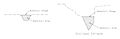
 750.3 Abutment and Pier Location Limits.gif 676 × 272; 5 KB
-
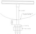
 750.3 Bottom of Footing Placement.gif 744 × 500; 25 KB
-
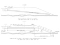
 750.3 Typical Excavation for a Flood Channel.gif 701 × 221; 7 KB
-
 750.4.4.6.jpg 852 × 225; 23 KB
-
 750.6.5.jpg 1,057 × 1,287; 422 KB
-
 750.6.jpg 647 × 776; 152 KB
-
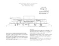
 750.6 Hydraulic Performance of an Energy Dissipating Headwall.pdf 1,275 × 1,650; 23 KB
-
 750.6 Stability of Natural Channels at Culvert Outlet.pdf 1,275 × 1,650, 2 pages; 19 KB
-
 750.7.13 Slopes for Skewed Culvert Sections.pdf 2,750 × 2,125, 2 pages; 112 KB
-
 750.7.3.2.jpg 948 × 629; 82 KB
-
 750.7.3.3.jpg 938 × 309; 24 KB
-
 750.7.3.3 USDA RM245.pdf 1,275 × 1,650; 7 KB
-
 750.7.3.jpg 870 × 281; 22 KB
-
 750.7 Culvert Extensions.pdf 1,650 × 1,275, 8 pages; 415 KB
-
 750.7 Maximum Limits for Class 3 and 4 Excavation.pdf 1,275 × 1,650; 7 KB
-
 750.7 Overfill Corrugated Metal Pipe-Arches.pdf 1,275 × 1,650; 28 KB
-
 750.7 Overfill Structural Plate Pipe.pdf 1,275 × 1,650; 37 KB
-
 750.7 Pipe Grades For Median Drop Inlets.pdf 1,558 × 1,183; 39 KB
-
 750.7 Slopes for Skewed Culvert Sections.pdf 1,275 × 1,650; 7 KB
-
 750.7 Upper Limits Of Class 3 Excavation.pdf 1,275 × 1,650; 7 KB


