751.12 Barriers, Railings, Curbs and Fences
To be found eligible for Federal-aid funding, new roadside safety devices should meet the crash test and evaluation criteria contained in the American Association of State Highway and Transportation Officials’ (AASHTO) Manual for Assessing Safety Hardware (MASH). Since neither FHWA nor AASHTO has a system in place to approve roadside devices, the responsibility is left with the States. In response, MoDOT has developed a MASH Implementation process. All roadside devices that are submitted after November 1, 2019, will be reviewed by the MASH Team for approval to use on Missouri roadways. Prior to November 1, 2019 roadside devices were considered using the criterion set forth in NCHRP Report 350 “Recommended Procedures for the Safety Performance Evaluation of Highway Features”. While MASH requirements are only applicable to the NHS, the following guidelines are recommended for all bridges.
| See SEG 21-01, Anchoring Barriers Over Precast Panels. |
AASHTO LRFD uses the term “railing” to refer to all types of bridge traffic barrier systems used on bridges. MoDOT uses the term “barrier” for solid concrete bridge railing (single-faced on the edge of roadway and dual-faced medians) and the term “railing” for barrier systems consisting of a rail(s) and supports.
Contents
- 1 751.12.1 Concrete Barriers
- 1.1 751.12.1.1 Material Properties
- 1.2 751.12.1.2 General Details
- 1.3 751.12.1.3 Type D and H (42ʺ and 32ʺ single sloped railing)
- 1.3.1 751.12.1.3.1 Typical Section
- 1.3.2 751.12.1.3.2 Typical Section Reinforcement
- 1.3.3 751.12.1.3.3 End of Barrier Reinforcement
- 1.3.3.1 751.12.1.3.3.1 Type D Ending on Integral End Bents
- 1.3.3.2 751.12.1.3.3.2 Type H Ending on Integral End Bents
- 1.3.3.3 751.12.1.3.3.3 Type D Ending on Shallow Integral End Bents
- 1.3.3.4 751.12.1.3.3.4 Type H Ending on Shallow Integral End Bents
- 1.3.3.5 751.12.1.3.3.5 Type D Ending on Non-Integral End Bents
- 1.3.3.6 751.12.1.3.3.6 Type H Ending on Non-Integral End Bents
- 1.3.3.7 751.12.1.3.3.7 Type D Ending at End of Slab (Redecks)
- 1.3.3.8 751.12.1.3.3.8 Type H Ending at End of Slab (Redecks)
- 1.4 751.12.1.4 Type B (32ʺ New Jersey Shaped Railing)
- 1.5 751.12.1.5 Type C (42ʺ Single Sloped Median)
- 1.6 751.12.1.6 Type A (32ʺ New Jersey Shaped Median)
- 2 751.12.2 Two Tube Rail (Top Mounted)
- 3 751.12.3 Median Curbs
- 4 751.12.4 Chain Link Fence
- 5 751.12.5 Decorative Pedestrian Fence
- 6 751.12.6 Culvert Guardrail (Top Mounted)
751.12.1 Concrete Barriers
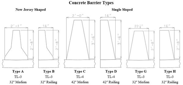
Type D barrier replaced Type B barrier (previously safety barrier curb) as the standard railing for bridges awarded after December 31, 2019. Similarly, Type C barrier replaced Type A barrier (previously median barrier curb). Types H and G shall be used respectively for situations where Types D and C is considered impractical.
Single sloped barriers have been shown to reduce vehicle climb and increase vehicle stability during redirections when compared to New Jersey shaped barriers. See the following sections for more details on standard barriers. Details for Type G have not been developed, but that does not prevent its use if need dictates.
Concrete barriers were approved for TL-3 or TL-4 test levels in accordance with the MASH 2016 standards. The required MASH 2016 test level for bridges on the National Highway System (NHS) is TL-3, but the expectation is that the TL-4 requirement will be mandated in the next publication.
Test level TL-3 is defined by AASHTO as being “generally acceptable for a wide range of high-speed arterial highways with very low mixtures of heavy vehicles and with favorable site conditions.”
Test level TL-4 is defined by AASHTO as being “generally acceptable for the majority of applications on high-speed highways, freeways, expressways, and interstate highways with a mixture of trucks and heavy vehicles”.
751.12.1.1 Material Properties
| Class B-1 Concrete | Epoxy Coated Reinforcing Steel | |
|---|---|---|
| Unit weight (reinforced), wc = 0.150 kcf | Yield strength, fy = 60.0 ksi | |
| Compressive strength, f’c = 4.0 ksi | Modulus of elasticity, Es = 29,000 ksi | |
| Modular ratio, n = 8 | ||
| Modulus of elasticity, Ec = 3644 ksi |
751.12.1.2 General Details
Regardless of type of barrier shown the following sections are applicable for all concrete barrier types.
Top of barrier shall be built parallel to grade with barrier joints (except at end bents) normal to grade.
All exposed edges of barrier shall have either a 1/2-inch radius or a 3/8-inch bevel, unless otherwise noted.
751.12.1.2.1 Slip Forming
Conventional or slip forming may be used except for situations where slip forming is considered impractical.
See barrier elevation sheets of the barrier standard drawings for the required details.
Slip forming is impractical for prestressed double-tee bridges.
Cross Bracing C Bars
Slip forming requires two No. 5 cross bracing C bars located each side of all joints and at barrier ends.
List C bars in the Bill of Reinforcing Steel and note that bars are for the slip-formed option only.
For barrier segments on top of the bridge deck, use 12-foot C1 bars.
For barrier segments on top of the end bent wings (Type B, D or H):
- For segment lengths less than 14'-4", use C2 bars with the following lengths:
Barrier Segment Length 8' to < 9' 9' to < 10' 10' to < 11' 11' to < 12' 12' to < 13' 13' to <14'-4" Bar Length 5'-9" 6'-9" 7'-9" 8'-9" 9'-9" 10'-6"
- For segment lengths 14'-4" to 18 feet, use 12-foot C1 bars.
- For section greater than 18 feet, use two sets of 8-foot C2 bars.
Textured Fiberglass Bars
Slip forming requires three four-feet long No. 4 textured fiberglass bars centered at each joint.
751.12.1.2.2 Joints
See barrier elevation sheets of the barrier standard drawings for the required details.
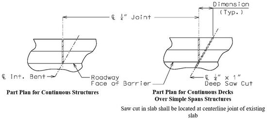
One-fourth-inch joints are located in the barrier at locations of negative moments to prevent cracking in the barrier. Barrier joints may be formed using ¼-inch joint filler in accordance with Sec 1057 or saw cut and seal with silicone joint sealant in accordance with Sec 717. Saw cuts joints may be used with the conventional forming option.
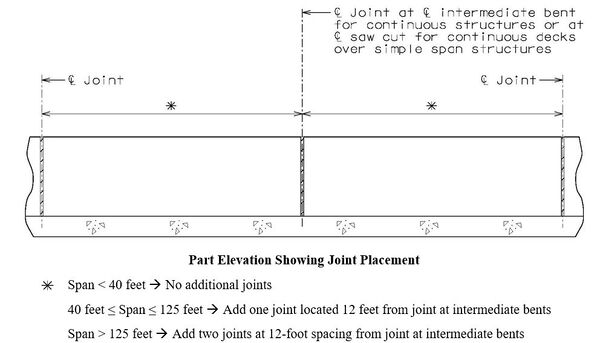
Joints are required when decks are continuous over intermediate bents for both continuous and simple span structures. These joints are also required at the front face of integral end bents. For placement of barrier joints at integral end bents see integral end bent details.
Additional joints at 12-foot spacing from joint at intermediate bents may be required based on span lengths. The following details provide guidance on locating flexural joints near intermediate bents. This spacing will allow the full yield-line failure pattern to develop for Type D barrier. For simplicity, the 12-foot spacing shall also be used for all other concrete barrier types.
751.12.1.2.3 Plastic Waterstops
See barrier elevation sheets of the barrier standard drawings for the required details.
Plastic waterstops are typically located inside formed joints to eliminate water seepage problems on grade separations. They shall be excluded over railroads and county roads and are only required on the lower side of superelevated decks.
751.12.1.2.4 Guardrail Attachment
See barrier at end bents sheets of the barrier standard drawings for the required details.
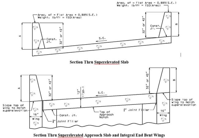
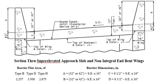
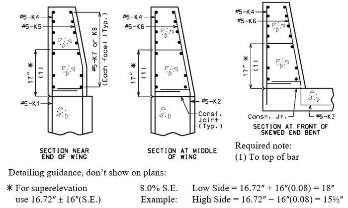
751.12.1.2.5 Superelevation
Superelevated slope, S.E., is in decimal format for the follow calculation, i.e. use 0.04 for 4.0%.
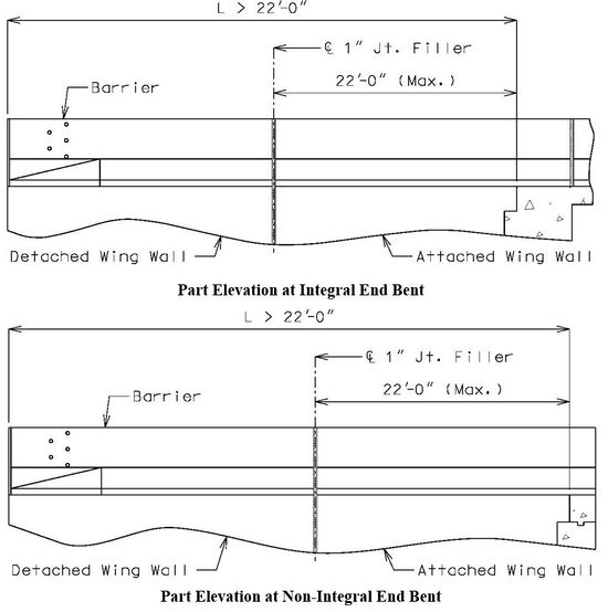
751.12.1.2.6 Detached Wing Walls
If the detached wing wall has more than one section, see the Structural Project Manager for possible additional joints in the barrier (between sections).
The following details are for illustration purposes only:
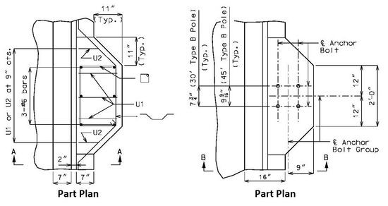
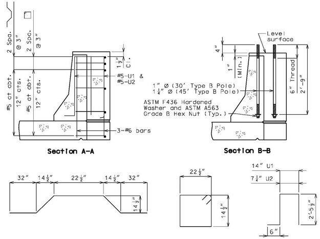
751.12.1.2.7 Details of Mounting Light Poles on Safety Barrier Curbs
Anchor bolts and nuts shall be in accordance with ASTM F1554 Grade 55. Anchor bolts, nuts and washers shall be fully galvanized, See 751.50.H4.2.2 for additional information.
Note to Detailer: Extend slab transverse steel to edge of slab in blister region often shown with an additional detail with the slab details.
Note: Conduit not shown for clarity.
751.12.1.3 Type D and H (42ʺ and 32ʺ single sloped railing)
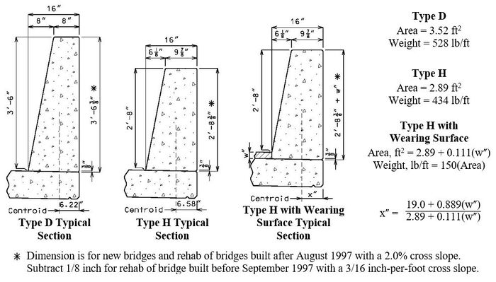
The 42-inch single sloped Type D barrier shall be used for railing on all new or replacement bridge projects except where sight distance is a concern. Type D meets the height requirements for both MASH 2016 TL-4 (36ʺ) and Occupational Safety and Health Administration’s OSHA (42ʺ). Type D barrier has been reviewed by the Midwest Roadside Safety Facility (MwRSF) and is compliant with MASH 2016 TL-4. This assessment is applicable for continuous and discontinuous sections of the barrier. Type D barrier shall be used on all redecks and rehabs where the full length of barrier is being replaced with exceptions as outlined in EPG 751.1.3.4 Barrier or Railing Type, Height and Guidelines for Curb Blockouts. The Type D barrier dimensions shall not be adjusted for inclusion of a wearing surface.
The 32-inch single sloped Type H barrier shall be used for railing, upon approval of the SPM or SLE, on all new or replacement bridge projects where sight distance concerns prohibit the use of Type D. Type H has the same front face slope as Type D. The minimum height for MASH 2016 TL-3 is 30 inches so there are minimal concerns with Type H for future overlays. Type H barrier has been reviewed by the Midwest Roadside Safety Facility (MwRSF) and is compliant with MASH 2016 TL-3. This assessment is applicable for continuous and discontinuous sections of the barrier. When a wearing surface is applied with the newly constructed Type H barrier, a pedestal is recommended to keep the holes for the guardrail attachment in the same location with respect to the top of the barrier.
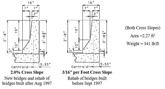
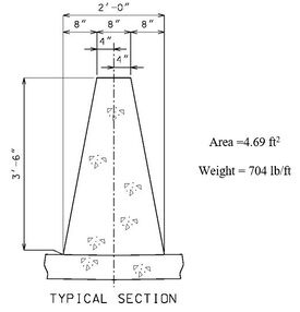
751.12.1.3.1 Typical Section
All values may be used with both 2.0% and 3/16 inch-per-foot cross slopes.
See EPG 751.12.1.2.5 Superelevation for adjustment of values for different cross slopes.
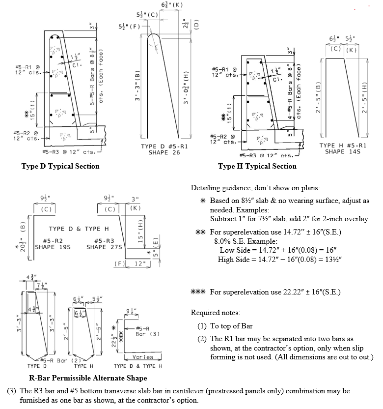
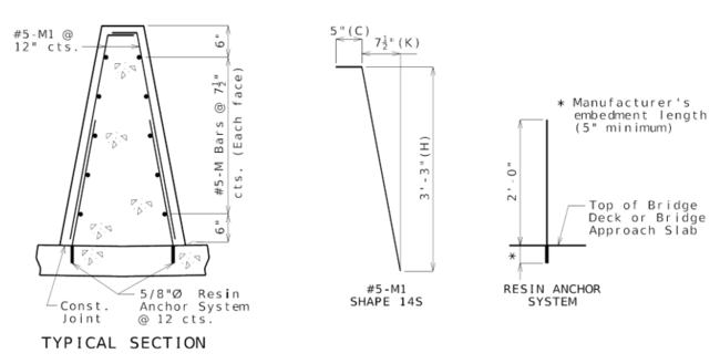
751.12.1.3.2 Typical Section Reinforcement
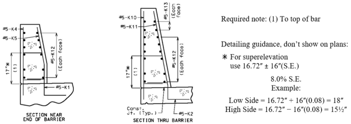
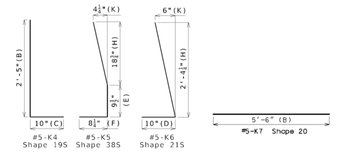
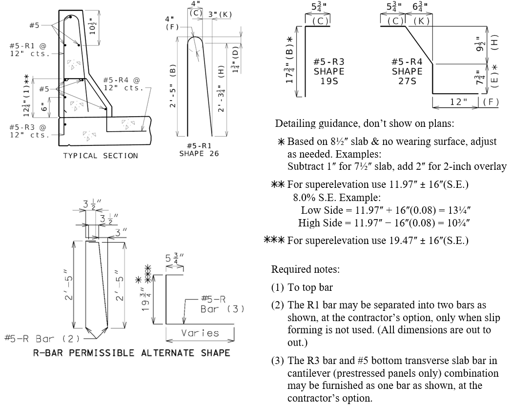
The single R bar adds to the rigidity of the reinforcement during construction and it is believed to help prevent cracking. The single bar also appears to assist maintaining uniform reinforcement cover.
Splice length for horizontal #5 bars in barrier curb shall be 37 inches.
All bent bars are formed using stirrup bends except for the Type D #5-R1 bars.
All values may be used with both 2.0% and 3/16 inch-per-foot cross slopes.
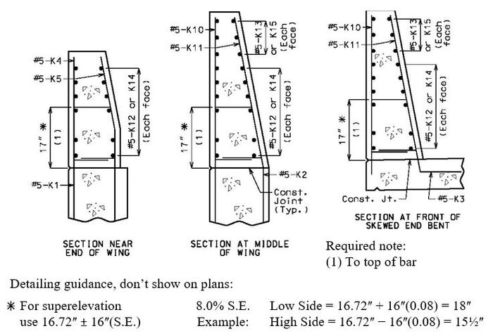
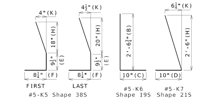
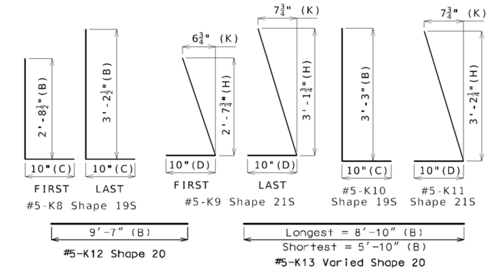
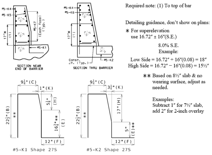
751.12.1.3.3 End of Barrier Reinforcement
See barrier standard drawings for the required details.
All bent bars are formed using stirrup bends.
All dimensions shown may be used with both 2.0% and 3/16 inch-per-foot cross slopes.
751.12.1.3.3.1 Type D Ending on Integral End Bents
Use when distance between upper and lower construction joint in wings is at least 28½ inches.
751.12.1.3.3.2 Type H Ending on Integral End Bents
Use when distance between upper and lower construction joint in wings is at least 28½ inches.
751.12.1.3.3.3 Type D Ending on Shallow Integral End Bents
Use when distance between upper and lower construction joint in wings is less than 28½ inches.
Formulas extend bars to within 1½ʺ of lower construction joint.
751.12.1.3.3.4 Type H Ending on Shallow Integral End Bents
Use when distance between upper and lower construction joint in wings is less than 28½ inches.
Formulas extend bars to within 1½ʺ of lower construction joint.
751.12.1.3.3.5 Type D Ending on Non-Integral End Bents
Use when distance between upper and lower construction joint in wings is at least 28½ inches.
751.12.1.3.3.6 Type H Ending on Non-Integral End Bents
Use when distance between upper and lower construction joint in wings is at least 28½ inches.
751.12.1.3.3.7 Type D Ending at End of Slab (Redecks)
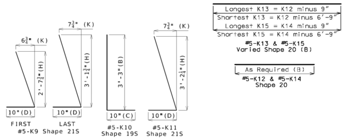
Splice length of #5 K12 and #5 K13 bars with #5 R-bars shall be 37 inches.
751.12.1.3.3.8 Type H Ending at End of Slab (Redecks)
Splice length of #5 K7 bars with #5 R-bars shall be 37 inches.
751.12.1.4 Type B (32ʺ New Jersey Shaped Railing)
The 32-inch New Jersey shaped railing, previously referred to as safety barrier curb, shall not be used on new construction projects. This includes redecks and rehabs where the full length of barrier is being replaced. Type B barrier may be replaced in kind where spot work is required (i.e., expansion joint replacements). For wearing surface projects, where the grade is not being increased more than 2 inches, the existing Type B barrier may be used in place in accordance with EPG 751.1.3.4.
751.12.1.4.1 Typical Section
See EPG 751.12.1.2.5 Superelevation for adjustment of values for different cross slopes.
751.12.1.4.2 Typical Section Reinforcement
The single R bar adds to the rigidity of the reinforcement during construction and it is believed to help prevent cracking. The single bar also appears to assist maintaining uniform reinforcement cover.
Splice length for horizontal #5 bars in barrier curb shall be 37 inches.
All bent bars are formed using stirrup bends except for the R1 bars.
751.12.1.4.3 End of Barrier Reinforcement
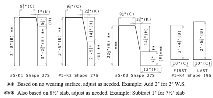
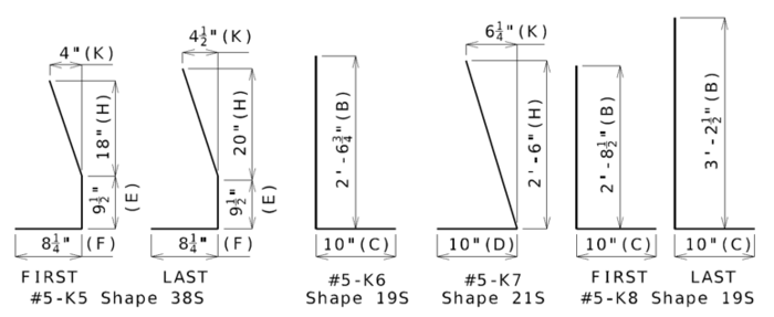
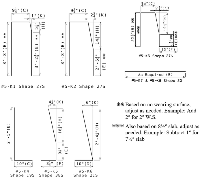
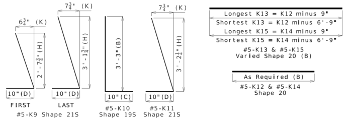
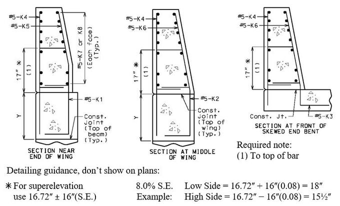
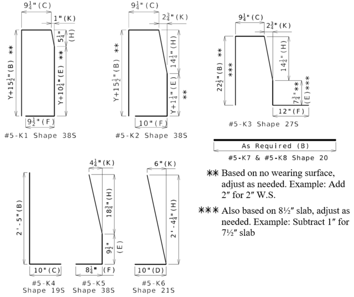
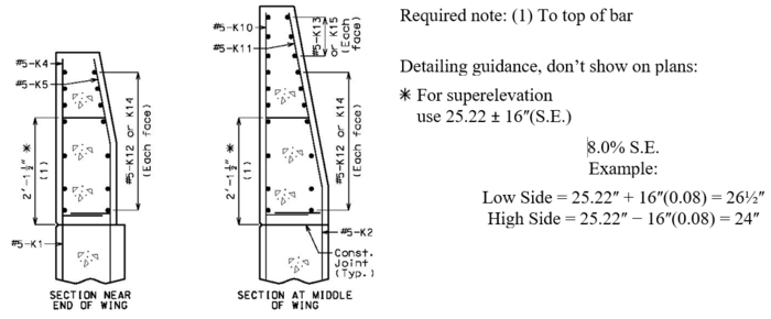
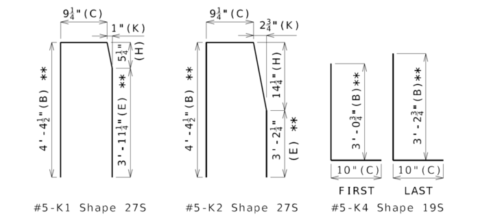
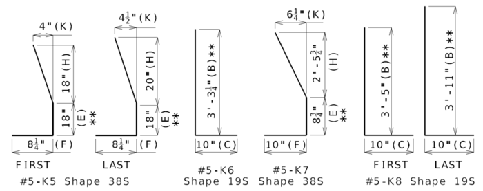
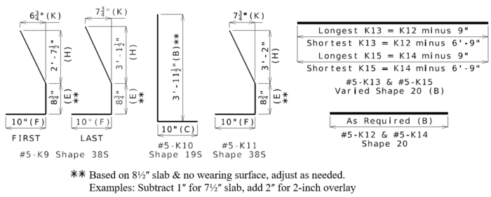
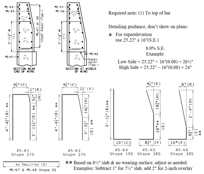
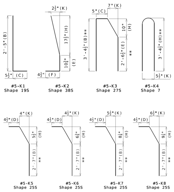
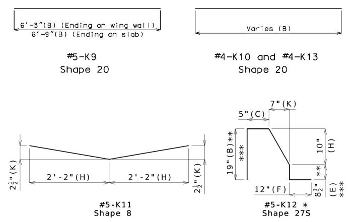
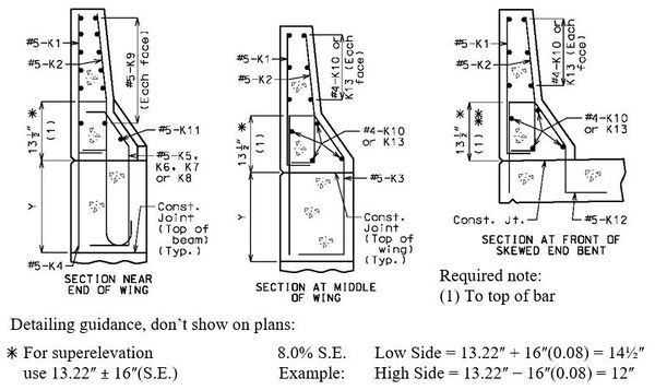
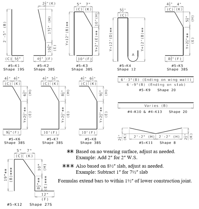
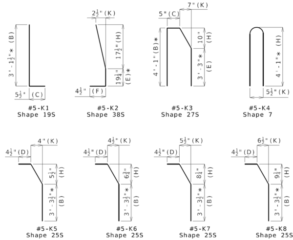
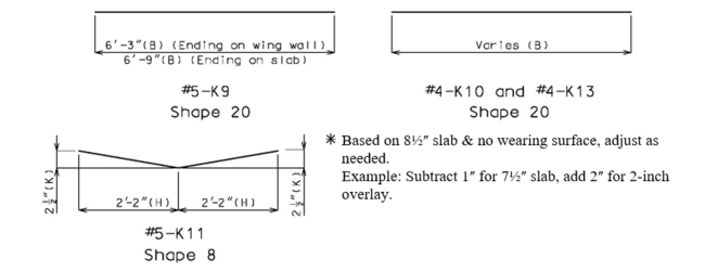
See barrier ending on end bents sheets of the barrier standard drawings for the required details. The bars shown below are for barrier ending on wing walls; see barrier ending at end of slab sheet of the barrier standard drawings for reinforcement details for barrier ending on slabs.
Splice length of #5-K9 bars with #4 K-bars above wing walls shall be 31 inches (embedment of #5 bars controls over splice length of #4 bars).
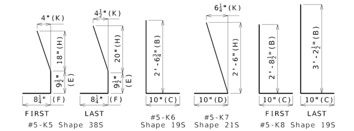
All bent bars are formed using stirrup bends except for the K4 and K11 bars.
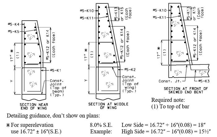
Ending on Integral End Bents and Semi-Deep Abutments
Use when distance between upper and lower construction joint in wings is at least 28½ inches.
- * On skewed integral end bents, if the end K3 bars do not meet the minimum 1 1/2" clearance from the front face of the diaphragm, a K12 bar shall be substituted.
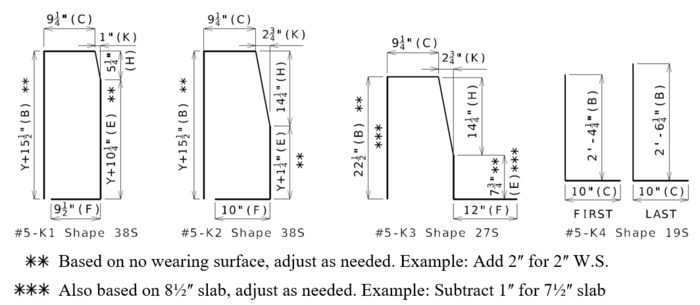
- * Based on no wearing surface, adjust as needed. Example: Add 2ʺ for 2ʺ W.S.
- * Also based on 8½ʺ slab, adjust as needed. Example: Subtract 1ʺ for 7½ʺ slab
Ending on Shallow Integral End Bents
Use when distance between upper and lower construction joint in wings is less than 28½ inches.
Ending on Non-Integral End Bents
Use when distance between upper and lower construction joint in wings is at least 28½ inches.
751.12.1.5 Type C (42ʺ Single Sloped Median)
751.12.1.5.1 Typical Section
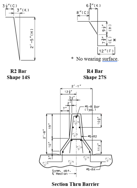
751.12.1.5.2 Typical Section Reinforcement
751.12.1.6 Type A (32ʺ New Jersey Shaped Median)
Note: Use same grade reinforcing steel in barrier as in slab.
- Splice length for #5-R bars in barrier = 37".
- Do not use this barrier over precast prestressed panels.
Twin Bridge Median Barrier Details
751.12.2 Two Tube Rail (Top Mounted)
38-inch Two Tube Rail
Consult the Structural Project Manager prior to use due to cost.
- Meets TL-4 (MASH 2016)
- May be used for decks not less than 6-1/2 inches.
- Uses an 18-inch wide curb. If the abutment uses turned-back wings they must be 18-inches thick.
- Acceptable for use when site distance is a concern.
- Requires the 38-inch Two Tube Rail Transition for the bridge approaches. See STD. Plan 606.61.
32-inch Two Tube Rail
Consult the Structural Project Manager prior to use due to cost.
- Meets TL-4 (NCHRP 350)
- Typically used on redecks, widenings, and railing or full-length cantilever replacements where the 38-inch Two Tube Rail is not practical.
- May be used on adjacent box beam bridges where reinforcement is embedded in the beam.
- Acceptable for use when roadway width or site distance is a concern.
- See EPG 751.1.3.4 Barrier or Railing Type, Height and Guidelines for Curb Blockouts for additional requirements for design speed and AADT.
- Curb is intrinsic to TL rating and shall be used. Curb shall be used to prevent drainage over deck.
- Requires a Bridge Anchor Section (STD. Plan 606.22) for bridge approaches minus the bearing and connector plates.
Details
| Bridge Standard Drawings |
| Two Tube Rail |
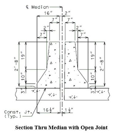
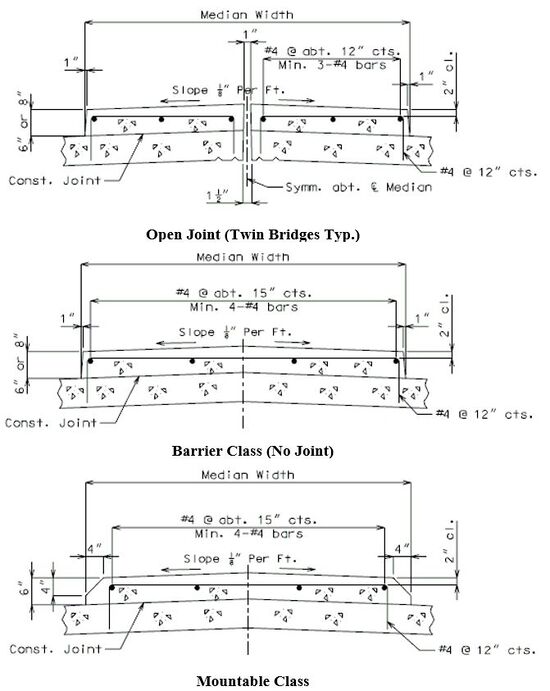
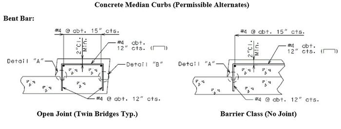
751.12.3 Median Curbs
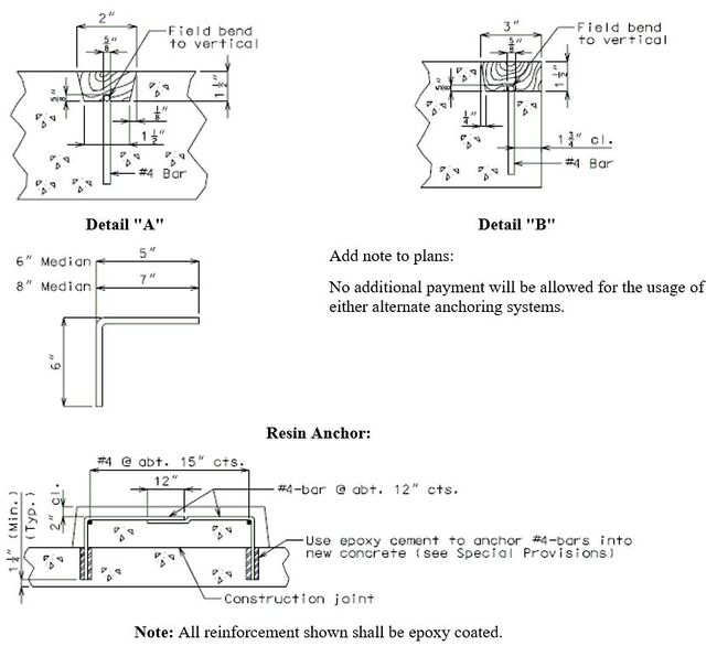
- Note: All reinforcement shown shall be epoxy coated.
Details shown are very general. Consult Design Layout for specific details for each individual structure.
751.12.4 Chain Link Fence
Design Criteria:
Dead load of fence fabric weight: 10 pounds per linear foot.
Wind load for chain link or metal fabric fence: GREATER OF 0.015 ksf acting normal to the entire surface per LRFD 13.8.2 OR 0.11 x entire surface x calculated wind pressure (11% is effective surface area per MoDOT practice).
| Bridge Standard Drawings |
| (Fences-FEN) |
751.12.5 Decorative Pedestrian Fence
751.12.5.1 Design
Decorative pedestrian fencing shall not be used without approval of the core team. Design of Decorative Pedestrian Fence is completed by consultant or contractor in accordance with LRFD 13. Bridge Pre-Qualified Products List contains a listing of decorative pedestrian fence manufacturers which have been approved for use.
General Guidelines
- Decorative Pedestrian fences are limited to minimum 3’-6” height from top of deck or sidewalk and maximum of 8’-0” post height.
- Decorative Pedestrian fences are limited to maximum 8’-0” post to post spacing.
- The base plate footprint shall match that provided in the Bridge Standard Drawings. A flat base plate is provided for decorative pedestrian fences located on Type H barriers and pedestrian curbs. Bent base plates are required for installations on Type B and Type D barriers due to the limited footprint available.
751.12.6 Culvert Guardrail (Top Mounted)
New Culverts
When a guardrail attachment is required for a new culvert, the guardrail shall be in accordance with the MASH TL-3 standard linked below. Listed below are a few of the requirements to meet MASH TL-3:
- 31-inch railing height measured between top of rail and finished grade
- 9 inches of minimum earth fill at back face of post
- 10-inch minimum clearance between headwall and post
- Guardrail shall be used on a maximum 10:1 slope. The 10:1 slope should be continued a minimum of 2 feet behind the post before using a steeper slope break.
- 6’-3” max post spacing
- Four 7/8-inch bolt pattern with 9-inch spacing in base plate
- 8-inch minimum embedment for resin-anchor option in 4 ksi concrete
- W6x9 steel post (W6x8.5 may be substituted)
- Specify Grade 36 steel for posts and base plates to match approach guardrail specifications. Anchorage is designed to resist forces for grade 50 substitution.
Note: The 10-inch minimum clearance to headwall is to ensure the post does not contact the headwall during a collision which may create a snag point for vehicles.
Existing Culverts
See EPG 751.1.3.4 Barrier or Railing Type, Height and Guidelines for Curb Blockout for culvert guardrail guidance.
