771.1 Concrete Bridge Approach Slab Repair: Slab Stabilization (Jacking)
| Code: R314 |
Jacking concrete bridge approach slabs is done to provide a smooth and safe transition, reduce impact from vehicles and fill voids under the concrete bridge approach slabs. The work is scheduled in October through May with temperatures between 35 to 70 degrees. This may include either mudjacking using a grout mixture for void filling/stabilization or polyurethane lifting (foamjacking) using polyurethane foam for slab lifting.
Contents
771.1.1 Materials
- Grout - Topsoil free of rocks, roots and debris mixed with 9 bags of cement per cubic yard. Fine sand or agricultural lime mixed with 6 bags of cement per cubic yard.
- Sufficient supply of water to mix with soil, sand, or lime to form thin grout.
- Tapered wooden plugs.
- Polyurethane Foam - proprietary and pre-approved (see PAL).
771.1.2 Procedures
New concrete bridge approach slabs beginning in 2018 are constructed without formed underseal access holes. New holes must be drilled, bored or cored. Prior to 2018, concrete bridge approach slabs (adopted in 1993) were constructed with formed underseal access holes. Reinforced concrete approach pavements (prior to 1993) were constructed without formed underseal access holes.
Mudjacking
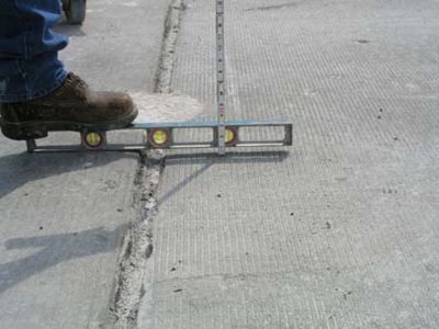
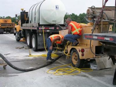
1. Bridge approach slabs should be monitored to determine the need for mudjacking. Settlement or voids along the slab edge are indicators of voids under the slabs.
2. Use an air drill to open existing holes or bore new ones.
3. Dampen pavement prior to pumping to make cleanup easier.
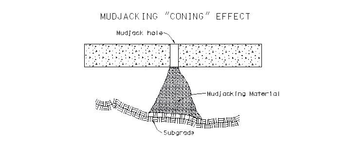
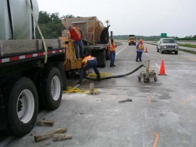
4. A thin mix of grout needs to be pumped in a systematic manner to avoid cracking the approach slab (See figure for details). If grout mix is too thick it will cause a coning effect and not fill the voided areas.
5. Mudjack holes may need to be plugged to continue filling voids or to raise the slab to correct grade.
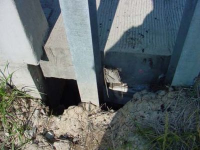
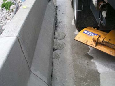
6. If a blowout develops during the pumping operation, try plugging it with the dry mudjack material. If this fails the operation may have to be halted to allow the grout under the slab to set, then return to complete the operation. Watch for blowouts along the shoulder lines, fill slopes, and at abutments.
7. When pumping operation is complete holes should be capped with mortar composed of 1 part cement and 3 parts sand to prevent moisture from entering the hole.
Polurethane Lifting (Foamjacking)
List procedures.
Optimized Combined Mudjacking and Foamjacking
Benefits can be realized by combining mudjacking and foamjacking since it will optimize material strengths and advantages at overall lower costs. It is cost effective to selectively use materials for their greatest intended purpose.
- - Grout is better for void-filling under slabs and stabilization at lower cost
- - Polyurethane is better for lifting slabs at higher cost
List procedures.
771.1.3 Safety
Use caution during pumping operations to avoid injury to employees and damage to private property.
771.1.4 Instructions
Mudjacking
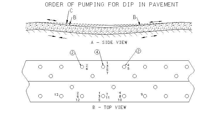
Holes may be present or will need to be drilled in the concrete pavement or bridge approach where the pavement has settled. The holes will be used to pump a slurry of material under the pavement to fill the voids and lift the slab back to its proper alignment.
The holes are normally 6 ft. apart and 3 ft. from the centerline and edges of the pavement. Trying to reduce the number of pumping holes, or increasing the distance between the holes could cause cracking of the pavement when the material is pumped under the slab.
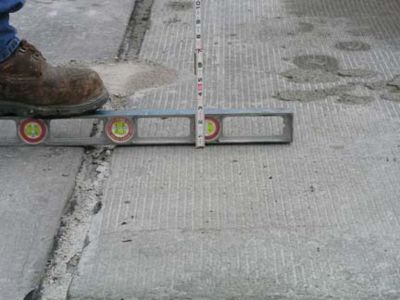
The holes will need to be located and drilled after inspecting the settled pavement. The pavement should not be raised more than 1/4 in. at any one time. It should be brought up slowly using several holes to pump the material that would raise the slab.
The diagram above shows the proper layout, location of the holes, and the pumping sequence.
The pumping and lifting sequence starts with pumping material into Hole 1 until some slight movement is noted in the slab. If pumping of the material continues without moving to another hole location it will cause cracking of the pavement.
The pumping then moves to the other hole locations in the sequence noted in the diagram. The goal is to raise the slab evenly to avoid cracking and to fill the voids underneath.
If the mudjacking material is too stiff it will build a cone or pyramid under the mudjack hole, and will prevent the material from filling the voids under the slab.
 |
|
| Bridge approach slabs should be monitored to determine the need for mudjacking. Settlement or voids along the slab edge are indicators of voids under the slabs. | |
 |
|
| A thin mix of grout needs to be pumped in a systematic manner to avoid cracking the approach slab. If grout mix is too thick it will cause a coning effect and not fill the voided areas. | |
 |
|
| Watch for blowouts along the shoulder lines, fill slopes and at abutments. | The approach should be brought up slowly to the proper alignment using several holes to pump the material. |
Polyurethane Lifting (Foamjacking)
UNDER DEVELOPMENT: List Instructions and show pictures.
Optimized Combined Mudjacking and Foamjacking
UNDER DEVELOPMENT: List instruction for combining mudjacking and foamjacking and show pictures.
771.1.5 Criteria for Initiating Repair Operations
New Bridge Approach Slabs
- In 2018, new concrete bridge approach slabs are no longer constructed with formed underseal access (or mudjack) holes. They may be required to be drilled by the contractor to permit investigation by the engineer of any suspected voids or cavities in accordance with Sec 503.
- Because drilling underseal access holes in a new bridge approach slab is undesirable, inspection of the sub-grade before the concrete pour is critical.
- Prior to acceptance, visual inspection for settlement is also critical. See Sec 503.
Older Settling Bridge Approach Slabs
- Noticeable changes can occur in ride smoothness at the end of bridges along an unspecified length of approach roadway leading up to the bridge. As a result, rider discomfort and vehicle impact effects to bridges and approaches can result.
- Often referred to as the “bump” at the end of the bridge, it is more technically understood to be a gradient caused by unequal support stiffness occurring within a transition zone between a settling roadway embankment and a non-settling rigid bridge abutment.
- The resulting gradient (or ramp) confirms that the bridge approach slab or any approach pavement for that matter is performing as expected.
- When the ramping becomes too severe or has been allowed to exist for too long, mudjackng may be required to restore support and lessen the ramp-effect (bump).
- Mudjacking is done to provide a smooth and safe transition, reduce impact from vehicles and fill voids under the concrete approach slabs.
- Slab or pavement deterioration may be visible in which case restoration of the slab or pavement may be required. If severe, replacement should be considered.
Mudjacking/Foamjacking
- Accounting for normal roadway grade changes as designed, a gradient between where one end of the ramp starts and the end of the bridge of 1” to 2” is considered the range at which point remedial action is necessary. This corresponds to gradients between 1/200 and 1/125 respectively for typical lengths of ramping observed (between 20 ft. and 30 ft.) where the former ratio represents the limit at which rider comfort begins to deteriorate and the latter ratio at which remedial action may be required.
- MoDOT prefers to initiate remedial action somewhere between these two limits. There are a number of factors used in prioritizing lifting work some of which are the working experience of the lifting team, traffic speed, AADT and truck traffic.
- Combined mudjacking and foamjacking is encouraged since it will optimize material strengths and advantages at overall lower costs.
- Work is typically scheduled in October through May with temperatures between 35 to 70 degrees.
Note:
- Some older bridges were not constructed with corbels (also referred to as approach notches). These are integral concrete notches built on the backside of a bridge abutment and used to support pavement or a bridge approach slab. Sometimes the corbels were unreinforced and can fail causing the pavement to drop at the bridge end creating a very abrupt bump (reversed ramping).
- It is equally important to note that many older bridges and some newer bridges may not have reinforced concrete approach pavement running up to the abutments nor a reinforced concrete bridge approach slabs (adopted circa 1993).
- In some situations, the bump at the end of the bridge can be filled by asphalt “wedging”, filling in the wedge area created by a settling pavement.
