Difference between revisions of "751.12 Barriers, Railings, Curbs and Fences"
m (→751.12.2.3 End Bent Reinforcement: Per BR, corrected dimensions for K5-K8 bars placed in end bent wings and extending into bridge barrier.) |
m (→751.12.2 Safety Barrier Bridge Curbs (NJ Shape): Per BR, revised to allow saw cut joints for conventional-formed barrier curbs.) |
||
| Line 176: | Line 176: | ||
=== 751.12.2.7 Joint Details === | === 751.12.2.7 Joint Details === | ||
| − | ''' | + | '''Expansion Joints.''' Openings required for expansion shall be provided in the barrier curb in conjunction with deck joints. For details of expansion joints in barrier curb see expansion device details. |
| − | '''Curb Joints.''' | + | '''Barrier Curb Joints.''' One-fourth inch joints are located in the barrier curb at locations of negative moments to prevent cracking in the barrier curb. These joints are required when decks are continuous over intermediate bents for both continuous and simple span structures. These joints are also required at the front face of integral end bents. For placement of curb joints at integral end bents see integral end bent details. The following details provide guidance on locating curb joints near intermediate bents. |
| − | [[image:751.12.2.7.jpg|center| | + | [[image:751.12.2.7.jpg|center|750px]] |
| + | <center> | ||
| + | {| style="margin: 1em auto 1em auto" | ||
| + | |- | ||
| + | |'''*'''||One space = 1/4 Span to nearest 1 in. increment (Span < 40 ft.) | ||
| + | |- | ||
| + | | ||One space = 10 ft. (Span = 40 ft. to 125 ft.) | ||
| + | |- | ||
| + | | ||Two spaces = 10 ft. (Span > 125 ft.) | ||
| + | |} | ||
| + | </center> | ||
| + | Joints for conventional-formed barrier curbs may be either formed joints filled with one-fourth inch joint filler or saw cut joints sealed with joint sealant and backer rods. | ||
| − | The details for curb joints are included on the [http://www.modot.org/business/standard_drawings2/Barrier_curbs_new_title_block.htm barrier curb standard drawings]. | + | Joints for slip-formed barrier curbs shall only be saw cut joints sealed with joint sealant and backer rods. |
| + | |||
| + | The details for saw cut and formed barrier curb joints are included on the [http://www.modot.org/business/standard_drawings2/Barrier_curbs_new_title_block.htm barrier curb standard drawings]. | ||
=== 751.12.2.8 Plastic Waterstop === | === 751.12.2.8 Plastic Waterstop === | ||
| Line 188: | Line 201: | ||
To eliminate water seepage problems, use a plastic waterstop, as specified, and in accordance with details shown below. | To eliminate water seepage problems, use a plastic waterstop, as specified, and in accordance with details shown below. | ||
| − | Use a plastic waterstop at all | + | Use a plastic waterstop at all formed barrier curb joints on grade separations, except over railroads and county roads. |
| − | + | ||
| − | Use a plastic waterstop on lower | + | Use a plastic waterstop on lower formed barrier curb joints only, for structures with superelevation on grade separations. |
The detail for plastic waterstop is included on the [http://www.modot.org/business/standard_drawings2/Barrier_curbs_new_title_block.htm barrier curb standard drawings]. The detail shall be removed if not required. | The detail for plastic waterstop is included on the [http://www.modot.org/business/standard_drawings2/Barrier_curbs_new_title_block.htm barrier curb standard drawings]. The detail shall be removed if not required. | ||
Revision as of 09:29, 31 August 2018
Contents
- 1 751.12.1 Standard Safety Barrier Bridge Curbs
- 2 751.12.2 Safety Barrier Bridge Curbs (NJ Shape)
- 2.1 751.12.2.1 General Design
- 2.2 751.12.2.2 Standard Reinforcement Details
- 2.3 751.12.2.3 End Bent Reinforcement
- 2.4 751.12.2.4 Slip-Form Reinforcement Details
- 2.5 751.12.2.5 SBC for Wing with Detached Wing Wall
- 2.6 751.12.2.6 Guardrail Attachment Detail
- 2.7 751.12.2.7 Joint Details
- 2.8 751.12.2.8 Plastic Waterstop
- 2.9 751.12.2.9 Details of Mounting Light Poles on Safety Barrier Curbs
- 2.10 751.12.2.10 Superelevation Details
- 3 751.12.3 Medians
- 4 751.12.4 Chain Link Fence
- 5 751.12.5 Two Tube Rail (Top Mounted) TL-4 (NCHRP 350)
751.12.1 Standard Safety Barrier Bridge Curbs
751.12.1.1 Standard Safety Barrier Curbs used in Missouri
| File:751.12 barrier curb - NJ Shape.gif | |
| Type A Test Level TL-4 |
Type B Test Level TL-4 |
| NJ Shape | |
|---|---|
| File:751.12 barrier curb - type c & d.gif | |
| Type C Test Level TL-5 |
Type D Test Level TL-4 (NCHRP 350) |
| Note: | For Type F (Temporary Barrier Curb), refer to Missouri Standard Plans 617.20. |
|---|---|
| For Thrie Beam Rails, see Widening & Repair information. | |
| See Structural Project Manager before using Type C or D barriers. |
751.12.2 Safety Barrier Bridge Curbs (NJ Shape)
751.12.2.1 General Design
New safety barrier curbs "shall be shown to be structurally and geometrically crashworthy". Therefore, the shape of the safety barrier curb is selected based on crash-tested, or equivalent crash-tested geometry.
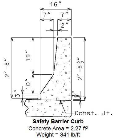
The safety barrier curb used on new bridges shall be the 16” New Jersey (MO) safety shape barrier curb which has been crash-tested and FHWA approved as meeting test level TL-4.
Test level TL-4 shall be used for safety barrier curb design. TL-4 is defined by AASHTO as being “generally acceptable for the majority of applications on high-speed highways, freeways, expressways, and interstate highways with a mixture of trucks and heavy vehicles”.
All exposed edges shall have either a 1/2-inch radius or a 3/8-inch bevel, unless otherwise noted.
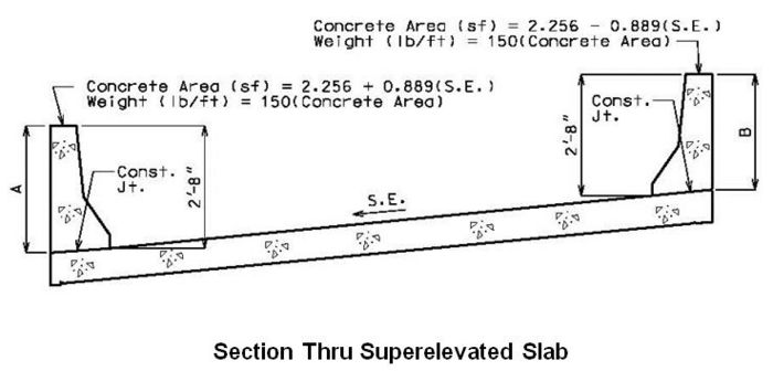
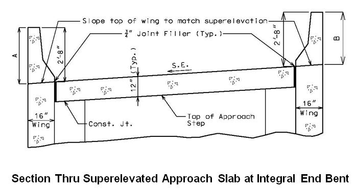
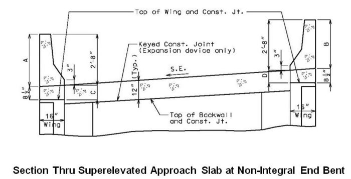
The values shown above are only applicable for the standard normal crown of two percent. See EPG 751.12.2.10 Superelevation Details for adjustment of values for different cross slopes.
| Concrete | |
|---|---|
| Unit weight of reinforced concrete, | = 150 |
| for modulus of elasticity, | = 145 |
| Safety Barrier Curbs | |
| Safety Barrier Curbs shall consist of: | |
| Class B-1 Concrete | = 4.0 ksi |
| = 8 | |
| Median Barrier Curbs | |
| Median Barrier Curbs shall consist of: | |
| Class B-1 Concrete | = 4.0 ksi |
| = 8 | |
| Reinforcing steel | |
| Minimum yield strength, | = 60.0 ksi |
| Steel modulus of elasticity | = 29000 ksi |
751.12.2.2 Standard Reinforcement Details
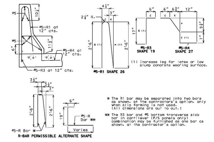
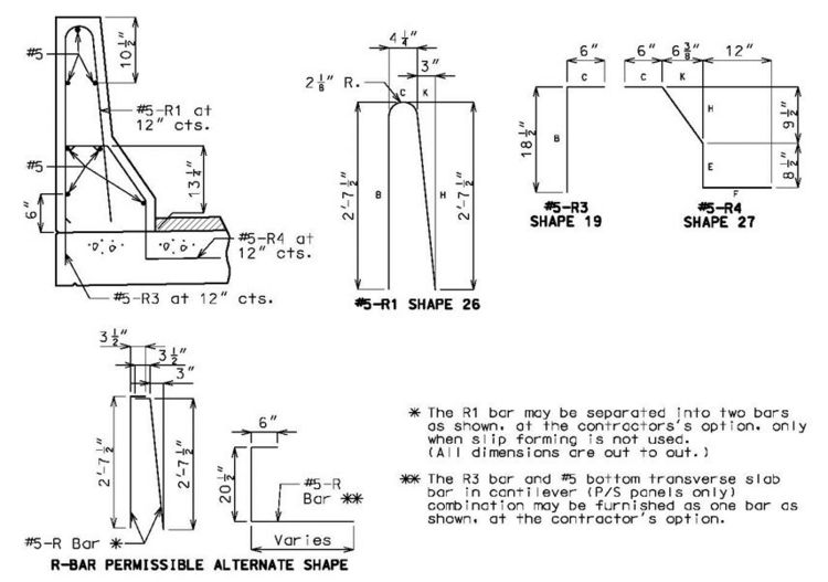
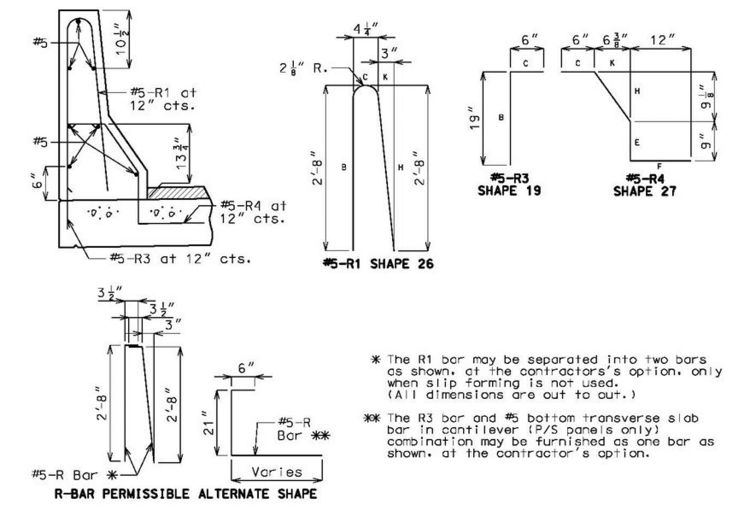
The single R bar adds to the rigidity of the reinforcement during construction and it is believed to help prevent cracking. The single bar also appears to assist maintaining uniform reinforcement cover.
Use same grade reinforcing steel in barrier curb as in slab.
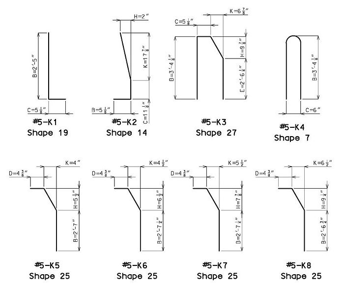
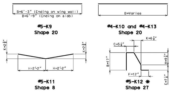
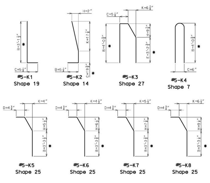
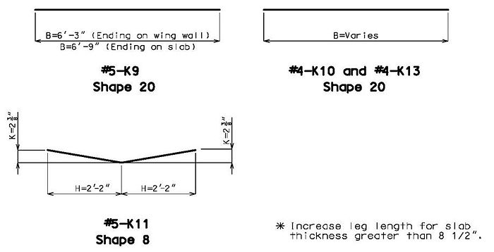
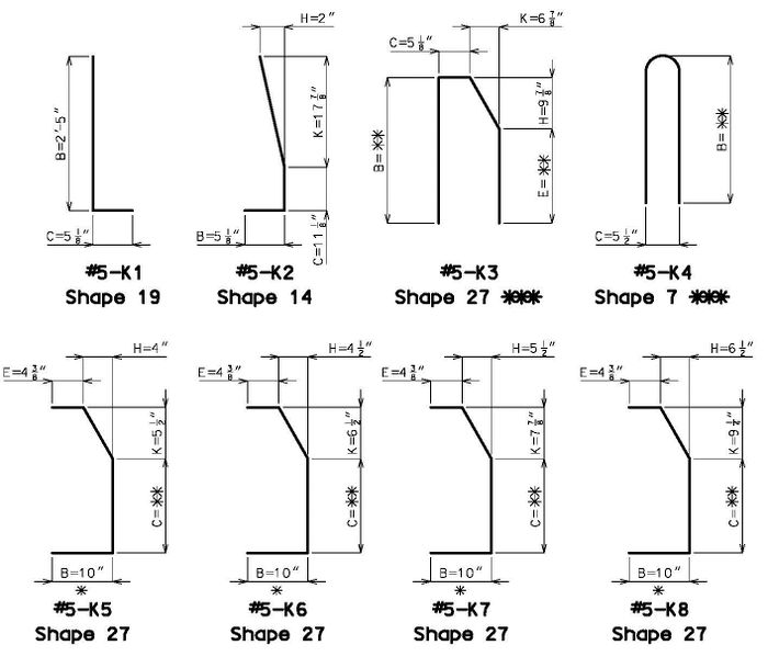
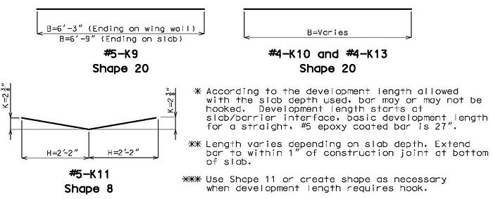
Splice length for #5 bars in barrier curb shall be 3’-1” except splice length of #5-K9 bars with #4 K-bars above wing walls shall be 2’-7” (embedment of #5 bars controls over splice length of #4 bars).
All bars are epoxy coated. All bent bars are formed using stirrup bends except for the R1, K4 and K11 bars.
(No Wearing Surface)
Dimensions shown are also typical for structures with latex or low slump concrete (except as indicated).
(1¾” Wearing Surface)
(2¼” Wearing Surface)
751.12.2.3 End Bent Reinforcement
See barrier curb standard drawings for the placement of the following reinforcement for barrier ending on wing walls. The dimensions shown below are for barrier ending on wing walls; see redecking templates for dimensions and placement of the reinforcement for barrier ending on slabs.
All bars are epoxy coated. All bent bars are formed using stirrup bends except for the K4 and K11 bars.
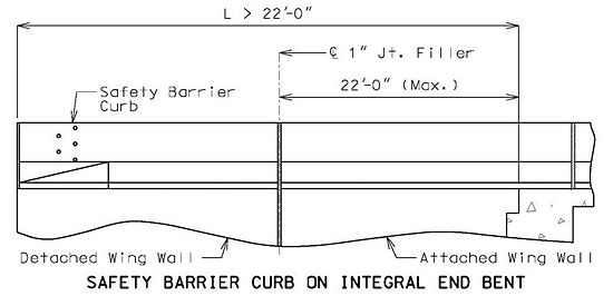
Integral End Bents and Semi-Deep Abutments
* On skewed integral end bents, if the end K3 bars do not meet the minimum 1 1/2" clearance from the front face of the diaphragm, a K12 bar shall be substituted.
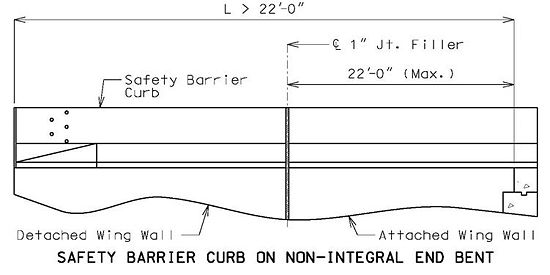
Non-Integral End Bents
Continuous Concrete Slab
751.12.2.4 Slip-Form Reinforcement Details
Optional slip-form safety barrier curb details shall be placed on all jobs (except prestressed double-tee structures) where applicable.
Add #5 cross bracing C bars for slip-form option.
In each span, the length of the C bars is based on the shortest distance between the joints for that span.
The length of the C bars above the wings (above the approach slab for median barriers) shall provide 1 1/2ʺ clearance to the joint at the end bent and 1 1/2ʺ clearance to the start of the transition for the guard rail attachment (to the end of the barrier for median barriers). A series of cross bracing C bars shall be used to limit the length of the C bars to 12 feet.
List C bars in the Bill of Reinforcing Steel and note that bars are for the slip-form option only.
See barrier curb standard drawings for the required details.
751.12.2.5 SBC for Wing with Detached Wing Wall
If the detached wing wall has more than one section, see the Structural Project Manager for possible additional joints in the safety barrier curb (between sections).
The following details are for illustration purpose only:
751.12.2.6 Guardrail Attachment Detail
See barrier curb standard drawings for the required details.
751.12.2.7 Joint Details
Expansion Joints. Openings required for expansion shall be provided in the barrier curb in conjunction with deck joints. For details of expansion joints in barrier curb see expansion device details.
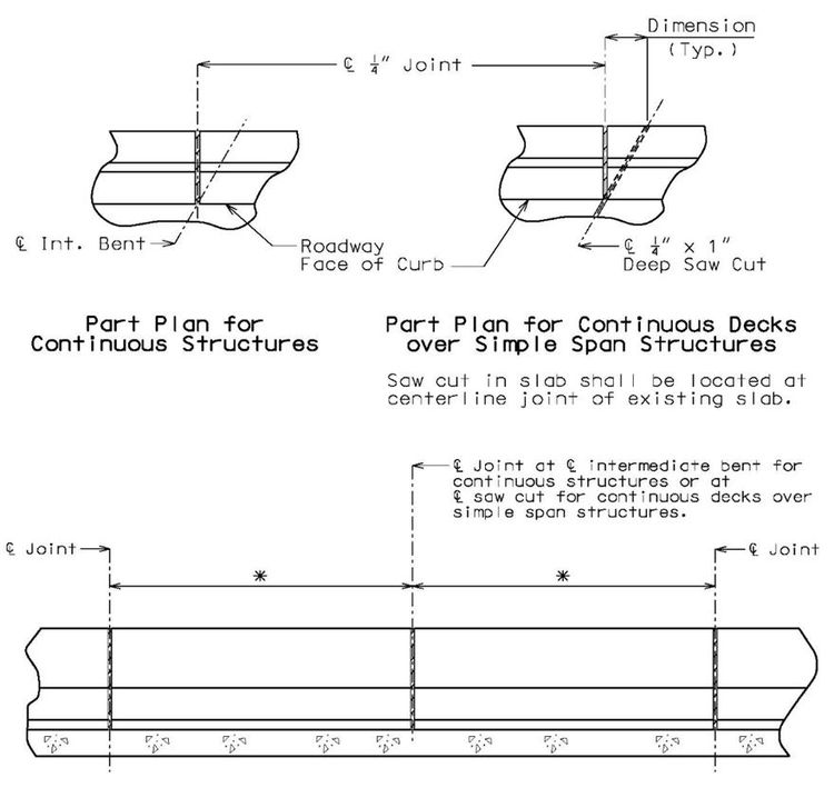
Barrier Curb Joints. One-fourth inch joints are located in the barrier curb at locations of negative moments to prevent cracking in the barrier curb. These joints are required when decks are continuous over intermediate bents for both continuous and simple span structures. These joints are also required at the front face of integral end bents. For placement of curb joints at integral end bents see integral end bent details. The following details provide guidance on locating curb joints near intermediate bents.
| * | One space = 1/4 Span to nearest 1 in. increment (Span < 40 ft.) |
| One space = 10 ft. (Span = 40 ft. to 125 ft.) | |
| Two spaces = 10 ft. (Span > 125 ft.) |
Joints for conventional-formed barrier curbs may be either formed joints filled with one-fourth inch joint filler or saw cut joints sealed with joint sealant and backer rods.
Joints for slip-formed barrier curbs shall only be saw cut joints sealed with joint sealant and backer rods.
The details for saw cut and formed barrier curb joints are included on the barrier curb standard drawings.
751.12.2.8 Plastic Waterstop
To eliminate water seepage problems, use a plastic waterstop, as specified, and in accordance with details shown below.
Use a plastic waterstop at all formed barrier curb joints on grade separations, except over railroads and county roads.
Use a plastic waterstop on lower formed barrier curb joints only, for structures with superelevation on grade separations.
The detail for plastic waterstop is included on the barrier curb standard drawings. The detail shall be removed if not required.
751.12.2.9 Details of Mounting Light Poles on Safety Barrier Curbs
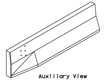
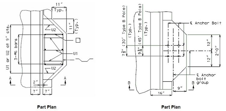
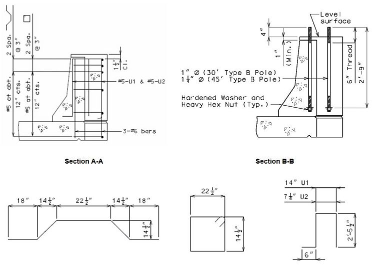
Anchor bolts and nuts shall be in accordance with ASTM A449. Anchor bolts, nuts and washers shall be fully galvanized.
Note to Detailer: Extend slab transverse steel to edge of slab in blister region often shown with an additional detail with the slab details.
Note: Conduit not shown for clarity.
751.12.2.10 Superelevation Details
| "A" | = 32'-8" + S.E. x 16" |
| B | = 32'-8" - S.E. x 16" |
| C | = 8 1/2" + S.E. x 16" |
| D | = 8 1/2" - S.E. x 16" |
751.12.3 Medians
751.12.3.1 Double Faced Median Barrier Curb (NJ Shape)
| Note: | Use same grade reinforcing steel in barrier curb as in slab. |
| Splice length for #5-R bars in barrier curb = 37". | |
| Do not use this barrier curb over precast prestressed panels. |
| Note to detailer: | Provide slip-form option for double faced median safety barrier curb. For slip-form option additional #5 cross bracing bars shall be placed on both sides of all joints and R2 bars shall be one bar. |
| File:751.12 double-faced median barrier curb reinforcement-r2 bar.gif | File:751.12 double-faced median barrier curb reinforcement-r4 bar.gif |
| R2 Bar Shape 15 |
R4 Bar Shape 27 |
|---|---|
| File:751.12 section thru double faced median barreir curb.gif | |
| Section Thru Double Faced Median Barrier Curb | |
| Twin Bridge Median Barrier Curb Details | |
| File:751.12 section thru median curb with open joint.gif | |
| Section Thru Median with Open Joint | |
751.12.3.2 Concrete Median Curbs
| File:751.12 concrete median curbs-open joint (twin bridges typ).gif |
| Open Joint (Twin Bridges Typ.) |
|---|
| File:751.12 concrete median curbs-barrier class (no joint).gif |
| Barrier Class (No Joint) |
| File:751.12 concrete median curbs-mountable class.gif |
| Mountable Class |
| Note: All reinforcement shown shall be epoxy coated. |
| Details shown are very general. Consult Design Layout for specific details for each individual structure. |
| Bent Bar: | |
| File:751.12 concrete median curbs (permissalbe alternates)-open joint (twin bridges typ.).gif | File:751.12 concrete median curbs (permissalbe alternates)-barrier class (no joint).gif |
| Open Joint (Twin Bridges Typ.) | Barrier Class (No Joint) |
|---|---|
| File:751.12 concrete median curbs (permissalbe alternates)-detail a.gif | File:751.12 concrete median curbs (permissalbe alternates)-detail b.gif |
| Detail "A" | Detail "B" |
| File:751.12 concrete median curbs (permissalbe alternates)-field bent bar.gif | Add note to plans: |
| No additional payment will be allowed for the usage of either alternate anchoring systems. | |
| Resin Anchor: | |
| File:751.12 concrete median curbs (permissalbe alternates)-resin anchor choice.gif | |
| Note: All reinforcement shown shall be epoxy coated. | |
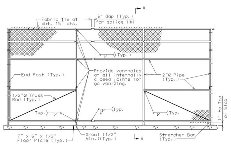
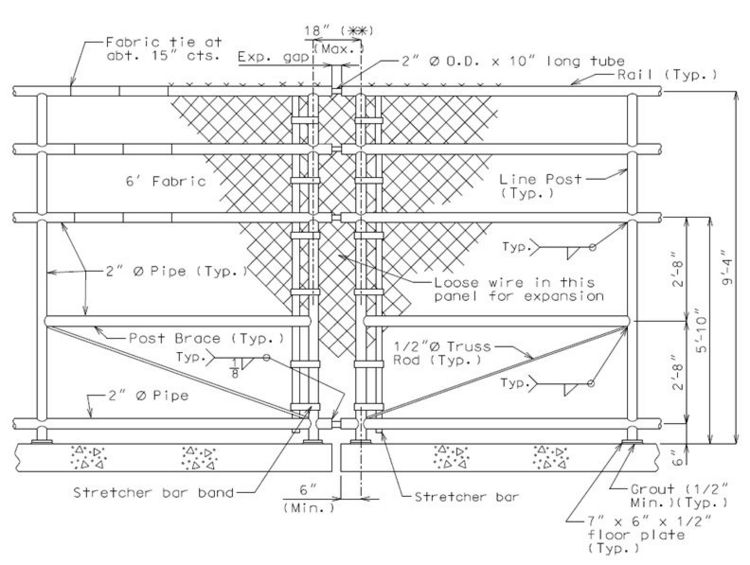
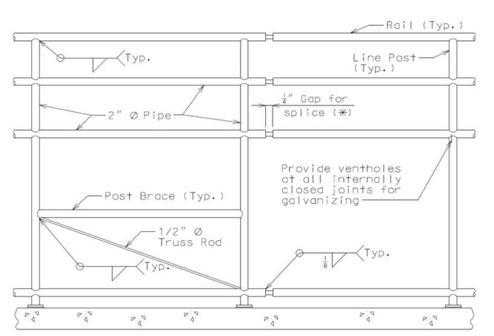
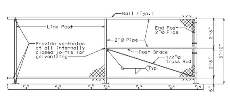
751.12.4 Chain Link Fence
Design Criteria:
Dead load of fence fabric weight: 10 lbs/lin. ft.
Wind load for chain link or metal fabric fence: GREATER OF 0.015 ksf acting normal to the entire surface per LRFD 13.8.2 OR 0.11 x entire surface x calculated wind pressure (11% is effective surface area per MoDOT practice).
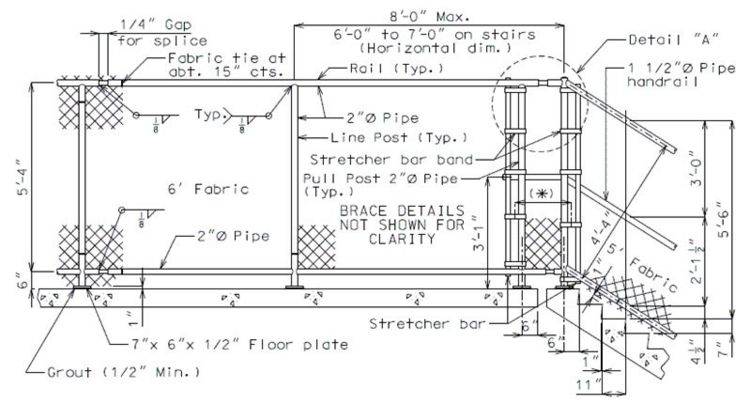
| |
| Superstructure Near Steps | |
|---|---|
| |
| Superstructure at or Near End Panel | |
| File:751.12 pedestrian overpass-superstructure near steps detail a.gif | |
| Detail "A" | |
| File:751.12 pedestrian overpass-landing.gif | File:751.12 pedestrian overpass-section thru fence.gif |
| Landing | Section thru Fence |
|---|---|
| |
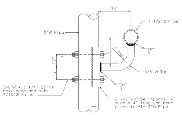
| Details of Handrail Bracket | |
| |
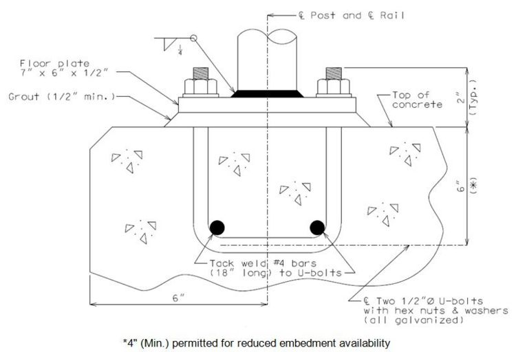
| Rail Post Connection (Typical) | |
| |
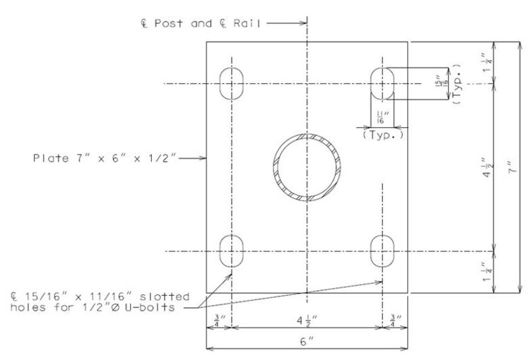
| Plan of Floor Plate | |
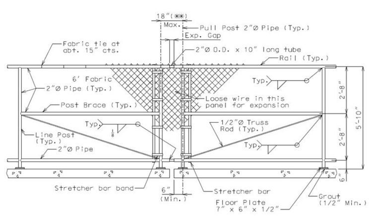
| |
| Details of Expansion Device Gap | |
| (**) May conflict with any proposed expansion device sidewalk, consult Structural Project Manager. | |
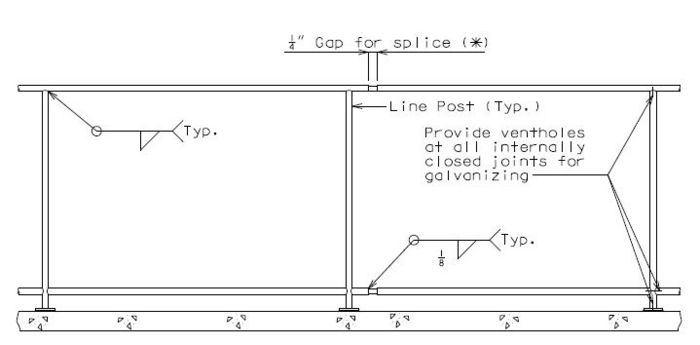
| |
| Typical Section Near Splice Gap | |
| Note: 8'-0" max. post spacing for superstructure.
(*) Locate at about 30'-0" centers with at least one splice gap between pull posts. (Add the following notes to the plans.) | |
751.12.5 Two Tube Rail (Top Mounted) TL-4 (NCHRP 350)
Guidance
- Meets TL-4 (NCHRP 350)
- Typically used on spread box beam bridges.
- May be used on adjacent box beam bridges where reinforcement is embedded in the beam.
- Use only in certain applications because of cost.
- Acceptable for use when roadway width or site distance is a concern.
- Curb is intrinsic to TL rating and shall be used. Curb shall be used to prevent drainage over deck.
Details
| Bridge Standard Drawings |
| Two Tube Rail |
