Category:610 Pavement Smoothness
Contents
610.1 International Roughness Index
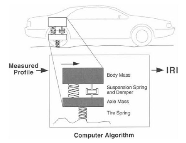
The International Roughness Index (IRI) has become the universal measure of pavement smoothness. IRI is derived from the true profile of the pavement surface. The road profile is composed of a combination of different wavelengths. Each wavelength stimulates a unique response to the axle/body configuration of a vehicle. Since no two vehicle types respond exactly the same to road roughness, it was necessary to select a single make and model, also known as the "golden car", to represent the average road response of commonly driven vehicles: mostly passenger cars, small pickup trucks and SUVs. In simple terms, IRI, measured in inches per mile (in/mi), is the mathematical sum of vertical displacements generated in the "golden car" by the frequency and amplitude of various wavelengths belonging to a specific length of pavement. The higher the IRI, the rougher the pavement is.
IRI measurements are required for all paving in Sec 401 (BP mixes), Sec 403 (Superpave mixes), Sec 502 (new PCC pavement) and Sec 506 (PCC pavement overlays). IRI measurements are not required for Sec 402 (SL mixes). Besides construction acceptance, MoDOT also uses IRI for annual roadway inventory data, both in the Tracker measure and the FHWA Highway Performance Monitoring System (HPMS).
610.2 Inertial Profilers (Sec 610.2.1)
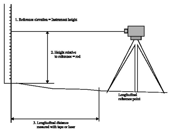
An inertial profiler is required to collect the true profile of a pavement. The true profile can be accurately collected with as simple a configuration as a basic rod and level. However, the short longitudinal distance required for each measurement (1 in. – 3 in.) to obtain acceptable wavelength resolution makes this method completely impractical.
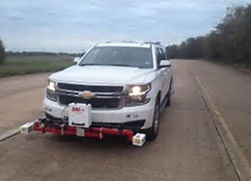
A practical method to collect short intervals of pavement elevation change is with an inertial profiler (IP). An IP can be mounted on a low speed utility vehicle or may be installed on the front, middle or rear of a high speed vehicle, such as a pickup truck. The quality of road profile data between a high speed IP and low speed IP should not vary significantly, if both pieces of equipment are properly calibrated. The obvious advantage of a high speed IP is the ability to collect data at normal operating speeds, so that a lane closure is not necessary.
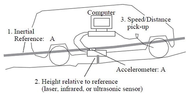
The core components of an IP are the
- 1) height sensor,
- 2) accelerometer,
- 3) distance measuring instrument (DMI) and
- 4) data processor.
Height sensors measure the distance above the pavement surface. There are different types of height sensors, but the most commonly used are lasers. Some IPs still have single point lasers, which occasionally may detect false readings of elevation changes in aggressive longitudinal pavement texture, such as grooving, because the laser point continually falls in and out of the texture valley. Most IPs now employ multiple laser configurations, which average out false readings from longitudinal texture.
Accelerometers filter out elevation changes induced by vertical acceleration from road roughness. In other words, an accelerometer provides information to the IP computer for the purpose of subtracting the artificial increase or decrease in elevation from bouncing, such that the remaining laser height measurement is the true elevation as if the vehicle were perfectly still over a specific point on the pavement.
DMIs measure the incremental distance traveled for each elevation reading. Combining the longitudinal distance component with the change in elevation provides all the information required to create the true profile of the pavement. Until recently, nearly all DMIs were mounted on one of the IP vehicle tires, relying on the rotation of the tire with a known circumference as the basis for measurement, hence, the reason maintaining IP manufacturer recommended tire pressures has always been stressed in IP operator training. If the tire pressures are too low or high, the tire circumference can change enough to induce errors in measured longitudinal distance. However, as expected, GPS technology has been introduced as a modern non-mechanical based method to measure longitudinal distance. Eventually, all tire-mounted DMIs will probably be replaced by a GPS-based system.
610.3 ProVAL Program (Sec 610.2.2)
The ProVAL program is required for pavement profile analysis. The software computes both average IRI per pavement segment and areas of localized roughness (ALR). Explicit instructions for running ProVAL are provided in EPG 106.3.2.59 TM-59, Determination of the IRI. The program may be downloaded for free at http://www.roadprofile.com/.
Each IP manufacturer has their own file format for pavement profiles, but all should be capable of creating a raw profile the .ppf file format. This is the preferred format in which all contractors shall submit raw profile data for analysis in ProVAL.
610.4 Smoothness Increments (Sec 610.4.1)
A section is the minimum length required for a contractor to attempt to grind into bonus. It is defined as a day’s paving, but may be broken into shorter, logical increments, such as before and after a structural crossing, at the engineer’s discretion. Typically, grinding an entire section would only be considered for a new concrete pavement or unbonded concrete overlay, but it is an available option on full depth and multi-lift overlay asphalt projects as well.
A segment is the fundamental unit length for pavement smoothness. The average IRI for each segment is independent of other segments for evaluation and pay adjustment purposes. All segments are 1/10th mile long (528 ft.), except for the very end of a profile run, which is either combined with the previous segment if ≤ 250 ft., or a standalone segment if > 250 feet.
610.5 IRI Measurements
IRI is measured in both wheel paths of a segment and averaged together for concrete and asphalt full depth pavement, concrete overlays, multi-lift asphalt overlays and combination texturing/single lift asphalt overlays. IRI is measured in only the right wheel path of a segment for single lift asphalt overlay and diamond grinding projects.
QC Testing – The contractor may elect to profile the pavement after paving on a daily basis or at the end of the project. Single lift overlays without pre-texturing also require a QC profile before the overlay. Once the contractor runs the IP, however; the raw profile file, in .ppf format, must be loaded on the project Sharepoint site within 24 hours. The MoDOT engineer is responsible for analyzing the file in ProVAL and copying the results to the IRI pay factor spreadsheet.
QA Testing – In order to provide a QC/QA comparison under nearly identical circumstances, the engineer shall delineate the beginning and ending of a pavement section within the project limits that is at least 10% of the total pavement length. It is best to select a section that has a minimum of interruptions, such as bridges, for testing continuity. The contractor shall run a QC profile within the exact limits of this section (regardless of whether or not the contractor had tested through the same limits earlier), then the engineer shall run a QA profile of the same section, ideally within seven days of the contractor test. The engineer shall analyze both files in ProVAL and copy the segment IRI numbers to the QC/QA comparison portion of the IRI pay factor spreadsheet.
The QC/QA analysis evaluates both the individual segment differences and the cumulative sum of the absolute values of the differences.
610.6 Areas of Localized Roughness (Sec 610.4.5.3)
Areas of localized roughness (ALR) are evaluated and addressed separately from segments. Loosely speaking, an ALR is a spot on the pavement that has a consistently high IRI using a 25 ft. rolling average. The MoDOT specification sets maximum ALR limits at either 125 (in/mi) or 175 (in/mi), depending on the operating speed and type of treatment. So an ALR exceeding 125 (in/mi) defines a point on the pavement profile that has an IRI ≥ 125 (in/mi) at any increment up to 12.5 ft. on either side. The length of the ALR depends on how far the rolling average at each adjacent increment is also ≥ 125 (in/mi).
ALRs are not measured for single-lift asphalt overlays, unless combined with texturing (i.e. milling, grinding) of the existing pavement.
The root causes of ALRs are variable. For new full depth pavement, they are virtually always construction-related. Construction headers, paver stops, etc are common causes. ALRs in thin overlay projects may occur through a combination of construction-related occurrences or existing geometric conditions.
All ALR locations must be identified through the ProVAL analysis. The MoDOT inspector should verify the locations by driving through the project. The engineer has the latitude to waive corrections to ALRs that are either insignificant, meaning not noticeably rough to a driver, or beyond the scope of what the project could conceivably correct. An example of the latter condition would be at an intersection on a letter route where the pavement crown is sharply thrown in and out of a superelevated profile. This would likely show up as an ALR in the ProVAL analysis. Unless the intersection had wedging corrections made prior to the overlay, the overlay by itself would not eliminate the ALR.
610.7 Dispute Resolution (Sec 610.5.5)
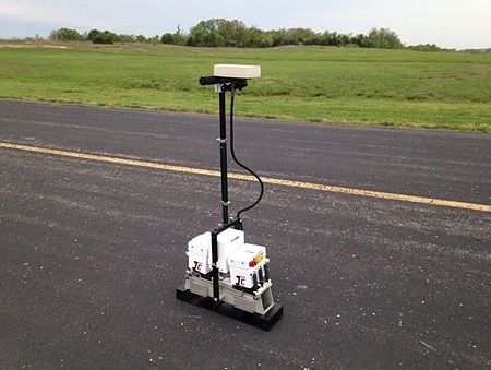
| MoDOT Reference Profiler |
MoDOT has a reference profiler that shall be used in the case of a dispute between QC and QA IRI results. A reference profiler has a higher level of accuracy than a conventional IP. The pavement section in dispute shall be run with the reference profiler. Whichever test result, QC or QA, is closer to the reference profiler IRI result shall stand as the correct profile determination.
MoDOT also uses its reference profiler as the ground truth basis for certifying IPs at the Linn State airport runway every year.
This category currently contains no pages or media.
