106.3.2.19 TM-19, Measurement of Pavement Surface Texture Depth by the Sand-Patch Method
This method describes a procedure for determining the average texture depth of a selected portion of a concrete pavement surface.
Contents
106.3.2.19.1 Apparatus

|

|

|

|
The apparatus shall consist of the following:
- (a) Sand spreading tool consisting of a 2 ½ in. diameter flat wooden disc with a 1/16 in. thick hard rubber disc of the same diameter attached to one face and a short dowel serving as a handle attached to the other face.
- (b) Metal cylinder with a volume of approximately 1.5 cu. in. (A cylinder 3.40 in. tall with an inside diameter of 0.75 in. has a volume of 1.50 cu. in.)
- (c) Natural silica sand from Ottawa, Illinois designated AFS 50/70 sand graded to pass a No. 40 sieve and retained on a No. 100 sieve, with 95% passing No. 50 Sieve.
- (d) Balance sensitive to 0.1 gram.
- (e) Ruler, 12 in. long with markings in divisions of every 0.1 in.
- (f) Wire brush and soft bristled hand brush.
- (g) Small plastic or metal containers for storing the required weight of sand for a single test. The container interior must be designed to permit emptying entire weight of sand for a single test. A 3 oz. tinned metal ointment box would be satisfactory.
106.3.2.19.2 Procedure
(a) Determine the exact volume, V, of the metal cylinder by weighing the water required to fill the cylinder and then calculating the volume in cubic inches. One cubic inch of water at 4°C weighs 16.4 grams.
Therefore, the following formula can be used to convert the net weight of water to volume.
- V =
(b) Using the following formula prepare a conversion table in which texture depths, T, can be determined for sand patch diameter, D, ranging from 4 to 12 in. with increments of 0.1 in.
- T =
- T = Texture Depth in inches
- V = Volume of metal cylinder in cubic inches
- D = Sand Patch diameter in inches
Conversion tables for cylinder volumes of 1.52 and 0.76 cu. in. are attached as examples. The weight of Ottawa AFS 50/70 sand required to fill these volumes is also shown on the tables and may be used for tests without additional volume or weight determinations.
(c) Determine the weight of sand needed to fill the metal cylinder. Fill the cylinder to the top with dry sand and gently tap the base of the cylinder three times on a rigid surface. Add sand to again fill the cylinder to the top then level the top with a straight edge. Obtain the net weight of sand to the nearest 0.1 gram.
Repeat this procedure a minimum of ten times to determine the average weight of sand required to fill the cylinder. This amount (weight) of sand should then be used for every sand patch test. Sand for several tests may be weighed in advance and stored in the small plastic or metal containers.
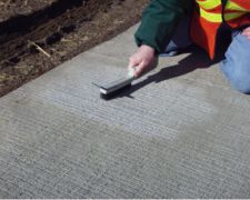
(d) The pavement surface selected for tests must be dry. If the concrete pavement has not been subjected to traffic, scrub the test surface with a wire brush to remove any loosely bonded particles or curing compounds chat will be worn away by a small amount of traffic. Otherwise, the pavement surface should be swept with a soft hand brush. Care should be taken on concrete surfaces tested at an early age. Excessive brushing or scrubbing will alter the surface texture.
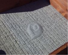
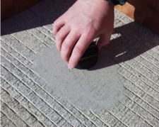
(e) Pour the previously measured weight of sand on the test surface and spread it with the rubber disc spreading tool into a circular patch until the surface depressions are filled to the level of the peaks. The sand spreading tool should be kept flat on the surface and moved in a circular motion. Avoid losing any sand, especially during windy conditions. Sand used for one test should not be reused for another test.
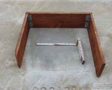
(f) Measure the diameter of the sand patch at four or more equally spaced locations and record to the nearest 0.1 in. For textured pavement surfaces with texture depths ranging from 0.020 to 0.040 in., 1.5 cubic in. of sand will produce patch diameters ranging between 7 and 10 in. For larger patch diameters, it becomes more difficult to obtain proper distribution of the sand as outlined in the previous paragraph. Much better distribution of the sand can be obtained by using approximately one-half the volume of sand (0.75 cu. in.). For texture depths ranging from 0.020 to 0.040 in., a volume of 0.75 cu. in. of sand produces patch diameters ranging between 5 and 7 in.
(g) Calculation of Texture Depth.
Compute the average diameter of the sand patch from the measured diameters, then determine the texture depth by using the computed conversion table or by use of the formula:
- T =
106.3.2.19.3 Report
The report shall contain:
(a) The date of test
(b) The location of the test (County, Route, Project, Station Number, Lane Designation, and Distance right or left of centerline)
(c) The average sand patch diameter
(d) The volume and weight of sand used
(e) The texture depth
(f) and Remarks.
Table 106.3.2.19 Sand Patch Test Method
| D | T | D | T | D | T | D | T | D | T | D | T | |
|---|---|---|---|---|---|---|---|---|---|---|---|---|
| 3.0 | .215 | 6.3 | .049 | 9.6 | .021 | 3.0 | .108 | 6.4 | .024 | 9.8 | .010 | |
| 3.1 | .201 | 6.4 | .047 | 9.7 | .021 | 3.1 | .101 | 6.5 | .023 | 9.9 | .010 | |
| 3.2 | .189 | 6.5 | .046 | 9.8 | .020 | 3.2 | .094 | 6.6 | .022 | 10.0 | .010 | |
| 3.3 | .178 | 6.6 | .044 | 9.9 | .020 | 3.3 | .089 | 6.7 | .022 | 10.1 | .009 | |
| 3.4 | .167 | 6.7 | .043 | 10.0 | .019 | 3.4 | .084 | 6.8 | .021 | 10.2 | .009 | |
| 3.5 | .158 | 6.8 | .042 | 10.1 | .019 | 3.5 | .079 | 6.9 | .020 | 10.3 | .009 | |
| 3.6 | .149 | 6.9 | .041 | 10.2 | .019 | 3.6 | .075 | 7.0 | .020 | 10.4 | .009 | |
| 3.7 | .141 | 7.0 | .039 | 10.3 | .018 | 3.7 | .071 | 7.1 | .019 | 10.5 | .009 | |
| 3.8 | .134 | 7.1 | .038 | 10.4 | .018 | 3.8 | .067 | 7.2 | .019 | 10.6 | .009 | |
| 3.9 | .127 | 7.2 | .037 | 10.5 | .018 | 3.9 | .064 | 7.3 | .018 | 10.7 | .008 | |
| 4.0 | .121 | 7.3 | .036 | 10.6 | .017 | 4.0 | .060 | 7.4 | .018 | 10.8 | .008 | |
| 4.1 | .115 | 7.4 | .035 | 10.7 | .017 | 4.1 | .058 | 7.5 | .017 | 10.9 | .008 | |
| 4.2 | .110 | 7.5 | .034 | 10.8 | .017 | 4.2 | .055 | 7.6 | .017 | 11.0 | .008 | |
| 4.3 | .105 | 7.6 | .034 | 10.9 | .016 | 4.3 | .052 | 7.7 | .016 | 11.1 | .008 | |
| 4.4 | .100 | 7.7 | .033 | 11.0 | .016 | 4.4 | .050 | 7.8 | .016 | 11.2 | .008 | |
| 4.5 | .096 | 7.8 | .032 | 11.1 | .016 | 4.5 | .048 | 7.9 | .015 | 11.3 | .008 | |
| 4.6 | .091 | 7.9 | .031 | 11.2 | .015 | 4.6 | .046 | 8.0 | .015 | 11.4 | .007 | |
| 4.7 | .088 | 8.0 | .030 | 11.3 | .015 | 4.7 | .044 | 8.1 | .015 | 11.5 | .007 | |
| 4.8 | .084 | 8.1 | .029 | 11.4 | .015 | 4.8 | .042 | 8.2 | .014 | 11.6 | .007 | |
| 4.9 | .081 | 8.2 | .029 | 11.5 | .015 | 4.9 | .040 | 8.3 | .014 | 11.7 | .007 | |
| 5.0 | .077 | 8.3 | .028 | 11.6 | .014 | 5.0 | .039 | 8.4 | .014 | 11.8 | .007 | |
| 5.1 | .074 | 8.4 | .027 | 11.7 | .014 | 5.1 | .037 | 8.5 | .013 | 11.9 | .007 | |
| 5.2 | .072 | 8.5 | .027 | 11.8 | .014 | 5.2 | .036 | 8.6 | .013 | 12.0 | .007 | |
| 5.3 | .069 | 8.6 | .026 | 11.9 | .014 | 5.3 | .034 | 8.7 | .013 | 12.1 | .007 | |
| 5.4 | .066 | 8.7 | .026 | 12.0 | .013 | 5.4 | .033 | 8.8 | .012 | 12.2 | .007 | |
| 5.5 | .064 | 8.8 | .025 | 12.1 | .013 | 5.5 | .032 | 8.9 | .012 | 12.3 | .006 | |
| 5.6 | .062 | 8.9 | .024 | 12.2 | .013 | 5.6 | .031 | 9.0 | .012 | 12.4 | .006 | |
| 5.7 | .060 | 9.0 | .024 | 12.3 | .013 | 5.7 | .030 | 9.1 | .012 | 12.5 | .006 | |
| 5.8 | .058 | 9.1 | .023 | 12.4 | .013 | 5.8 | .029 | 9.2 | .011 | 12.6 | .006 | |
| 5.9 | .056 | 9.2 | .023 | 12.5 | .012 | 5.9 | .028 | 9.3 | .011 | 12.7 | .006 | |
| 6.0 | .054 | 9.3 | .022 | 12.6 | .012 | 6.0 | .027 | 9.4 | .011 | 12.8 | .006 | |
| 6.1 | .052 | 9.4 | .022 | 6.1 | .026 | 9.5 | .011 | 12.9 | .006 | |||
| 6.2 | .050 | 9.5 | .021 | 6.2 | .025 | 9.6 | .010 | 13.0 | .006 | |||
| 6.3 | 0.24 | 9.7 | .010 | |||||||||

