617.2 Construction Inspection Guidelines for Sec 617

Permanent Concrete Traffic Barrier (for Sec 617.10) The several different types of permanent concrete traffic barrier are:
- Type A – is the conventional two-sided “New Jersey” barrier that has two slopes on the face.
- Type B – is a single-sided version of the Type A.
- Type B (MSE wall) – is a modified Type B used on MSE walls.
- Type C – is a two-sided single slope barrier.
- Type D – is a single-sided version of the Type C.
- Type D (MSE wall) – is a modified Type D used on MSE walls.
Type A and B barriers have a single rebar near the top of the barrier. Type C and D barriers have an extensive cage of reinforcing steel throughout the barrier.
Stepped versions of Types A and C are used where there is a difference in elevation in the median.
Material (for Sec 617.10.2) The inspector is to collect all necessary certifications for materials and/or check prequalified lists similar to the procedure for any other concrete pavement pour.
Construction Requirements (for Sec 617.10.3) The inspector is to perform all necessary quality assurance measures similar to the procedure for any other concrete pavement pour such as slump tests, air tests, etc. Check the plans ahead of time to find out what types of accommodations need to be made for any appurtenances such as guardrail, lighting or sign bases, drains, bridge columns, etc. Details on attachments are to be located in either the contract documents for customized items or in the respective section of the standard plans for standardized items.
For Sec 617.10.3.2 The shape of the concrete traffic barrier is critical since crash tests were performed on the specifically shaped barrier. Concrete traffic barrier is to be constructed to the dimensions shown in Standard Plan 617.10.
Prior to concrete placement, the inspector is to check that the placements of the steel reinforcement, bar sizes, clearances, etc. are according to the plans. Improper alignment of steel could cause the slipform machine to snag or later cause steel popouts. Bars are to be clean of any oil, concrete or other contaminants. The contractor are to mark joint locations prior to slipforming or pouring to minimize the possibility of cutting through steel when sawing joints later. The finished barrier is to be true to line and grade with a smooth and even appearance, free of honeycombed areas or cracks. The finished surface is to be textured, which is typically done with a broom.
Inspector's diaries are to contain sufficient notes to establish that any barrier constructed was built according to plan.
Temporary Concrete Traffic Barrier (for Sec 617.20)
Type F barrier with three loops is the latest crash-tested (NCHRP 350 tested) temporary barrier. The Type F barrier shall be used on all projects when a temporary barrier is specified.
Certification (for Sec 617.20.3) The inspector needs to collect certifications on Type F temporary concrete traffic barrier. The date of manufacture is stamped on the barrier. The date needs to be checked to verify certification. 617.20.4 Construction Requirements.
For Sec 617.20.4.1 Used Type F barriers are allowed on the job. If used barriers are brought on the job, they shall be inspected prior to being installed on a project. The inspector needs to make sure there is no exposed reinforcing steel, bent loops, large sections of concrete missing, significant cracks or other apparent defects that could impact the performance of the barrier.
It is the contractor’s responsibility to maintain the barrier in acceptable condition. The inspector must notify the contractor of any unacceptable pieces and ensure they are replaced in a reasonable fashion.
There are two variations of Type F barrier: two-loop version and the three-loop design. The use of two-loop Type F barrier shall be discontinued January 1, 2023.
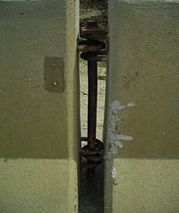
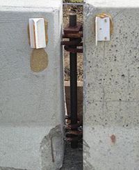
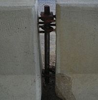
For Sec 617.20.4.2 The three-loop barrier uses a connection rod with an optional keeper pin assembly consisting, of a retainer bolt and nut and washer, to connect the sections. The use of the retainer bolt and nut and bottom washer is at the contractor’s option.
All exposed Type F barrier ends are to be protected with an approved end treatment. This may include a barrier flare, barrier height transition or crash cushion. Type F height transitions are not to be used where the posted speed prior to construction is greater than 35 mph.
When Type F barrier is hit, the localized area of impact usually bunches up several sections of barrier and makes connecting the barriers back together impossible without extending the barrier back out to its original location. Although overlapping of the barrier is acceptable at these locations, to be crashworthy the overlap needs to consist of , at minimum, six sections of barrier, i.e., 75 ft. (23 m) of barrier. Instead of requiring an overlap of 75 ft., it is recommended that the contractor be required, when possible, to extend the barrier back out to its original length thereby eliminating the overlap and allowing the units to be connected back together as designed. This can be accomplished without much effort if equipment (such as a forklift) operating to the rear of the barrier lift and push individual sections back together. If the barrier cannot be realigned, then the contractor will have no other choice but add sections to the barrier to provide the required 75-ft. overlap or to anchor the barrier.
If a contractor is interested in anchoring overlapping sections of barrier, contact Construction and Materials for details.
It is imperative that the Type F barrier be connected together as designed or properly anchored or overlapped when individual barrier sections cannot be properly pinned together. Anything less will not meet NCHRP 350 or MASH 2016.
For Sec 617.20.4.4 Equipment or material shall not be stored near temporary barriers within the limits shown on the plans or as approved by the engineer.
For Sec 617.20.4.5 Type F barrier may be anchored to the pavement and bridges as shown on the plans. The barrier is to be anchored on bridges when lateral deflection cannot be tolerated. The method of anchoring on bridge decks will be determined by Bridge and will be shown on the bridge plans.
Concrete Traffic Barrier Delineators (for Sec 617.30).
Material (for Sec 617.30.2) For permanent barrier installations, the inspector needs to collect certification on the sheeting used on the delineators and ensure that all delineators meet Sec 1065.
Construction Requirements (for Sec 617.30.3) The face of barrier is no longer painted by the contractor. The delineators take the place of painting the barriers. The delineators are used because they are more retroreflective, above the splash zone and are designed to adhere to the barrier better than paint. If temporary barriers are provided with existing painted faces, the painted face should turned away from traffic if possible or at least positioned so the existing painted face matches the color of the adjacent edgeline. Permanent barriers may be painted by district forces at the district’s discretion after the job is complete.


