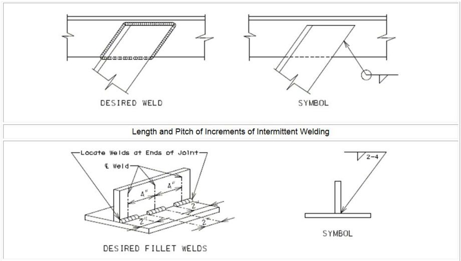
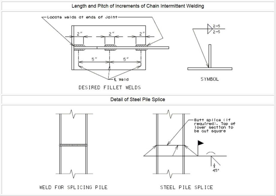
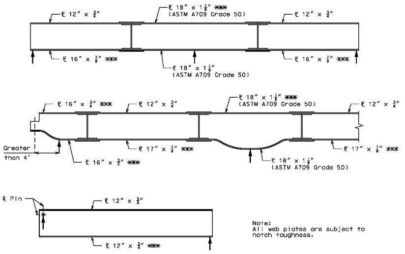
751.5 Structural Detailing Guidelines
The scope of this article is to provide preferred detailing practices for in-house structural drawings in order to reduce revisions based solely on personal preferences.
Contents
- 1 751.5.1 General Detailing
- 1.1 751.5.1.1 Drafting Standards
- 1.1.1 751.5.1.1.1 CADD Levels
- 1.1.2 751.5.1.1.2 Line Conventions
- 1.1.3 751.5.1.1.3 Annotation
- 1.1.4 751.5.1.1.4 Reference Notes
- 1.1.5 751.5.1.1.5 Sections, Elevations and Detail Circles
- 1.1.6 751.5.1.1.6 Hatching
- 1.1.7 751.5.1.1.7 Breaks
- 1.1.8 751.5.1.1.8 Surfaces
- 1.1.9 751.5.1.1.9 Text Height
- 1.1.10 751.5.1.1.10 Span Ranges
- 1.2 751.5.1.2 Weights and Measures
- 1.3 751.5.1.3 Grammar and Punctuation
- 1.4 751.5.1.4 Contract Plan File Name Convention
- 1.5 751.5.1.5 Order of Plan Sheets
- 1.6 751.5.1.6 Example Bridge Plan Sheets
- 1.7 751.5.1.7 Contract Addendums and Construction Changes
- 1.1 751.5.1.1 Drafting Standards
- 2 751.5.2 Location and Layout Sheets
- 2.1 751.5.2.1 Plan and General Elevation (Front Sheet)
- 2.1.1 751.5.2.1.1 Plan Detail
- 2.1.1.1 751.5.2.1.1.1 Substructure Elements
- 2.1.1.2 751.5.2.1.1.2 Skew Detail
- 2.1.1.3 751.5.2.1.1.3 Boring Locations
- 2.1.1.4 751.5.2.1.1.4 Bridge Roadway Width
- 2.1.1.5 751.5.2.1.1.5 Features Crossed
- 2.1.1.6 751.5.2.1.1.6 North Arrow and Curve Data
- 2.1.1.7 751.5.2.1.1.7 Miscellaneous Notes for the Plan Detail
- 2.1.1.8 751.5.2.1.1.8 Miscellaneous Details for the Plan Detail
- 2.1.2 751.5.2.1.2 General Elevation Detail
- 2.1.2.1 751.5.2.1.2.1 General Elevation View
- 2.1.2.2 751.5.2.1.2.2 Elevations
- 2.1.2.3 751.5.2.1.2.3 End of Slab
- 2.1.2.4 751.5.2.1.2.4 Bent Number and Fixity
- 2.1.2.5 751.5.2.1.2.5 Vertical Alignment Data
- 2.1.2.6 751.5.2.1.2.6 Ground Lines
- 2.1.2.7 751.5.2.1.2.7 Features Crossed
- 2.1.2.8 751.5.2.1.2.8 Slope Protection
- 2.1.2.9 751.5.2.1.2.9 Miscellaneous Notes for the General Elevation Detail
- 2.1.2.10 751.5.2.1.2.10 Miscellaneous Details for the General Elevation Detail
- 2.1.3 751.5.2.1.3 Information Blocks
- 2.1.4 751.5.2.1.4 Section Thru Existing Deck Detail
- 2.1.5 751.5.2.1.5 Supplementary Details
- 2.1.1 751.5.2.1.1 Plan Detail
- 2.2 751.5.2.2 General Notes and Estimated Quantities
- 2.3 751.5.2.3 Staged Construction
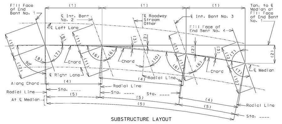
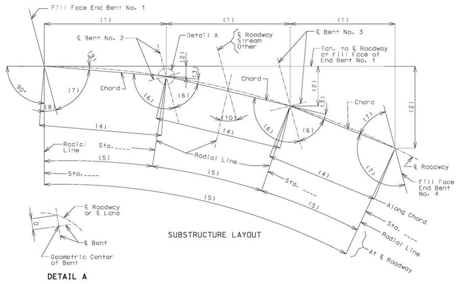
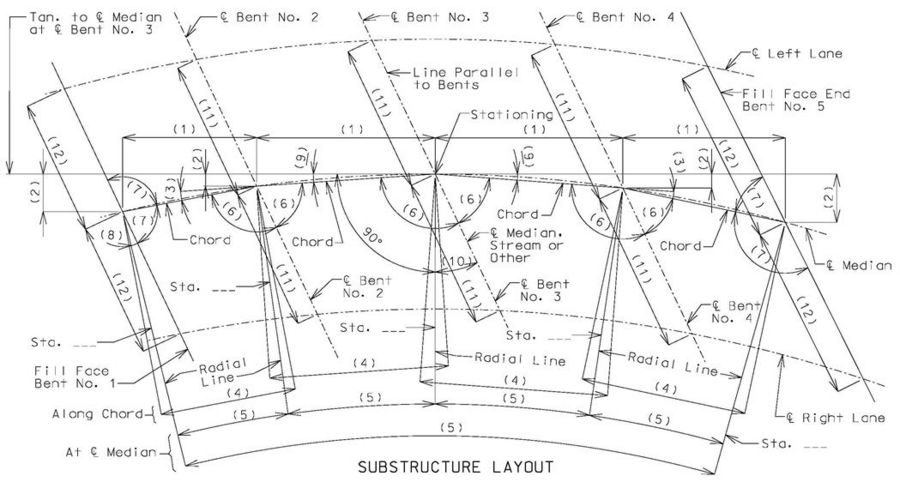
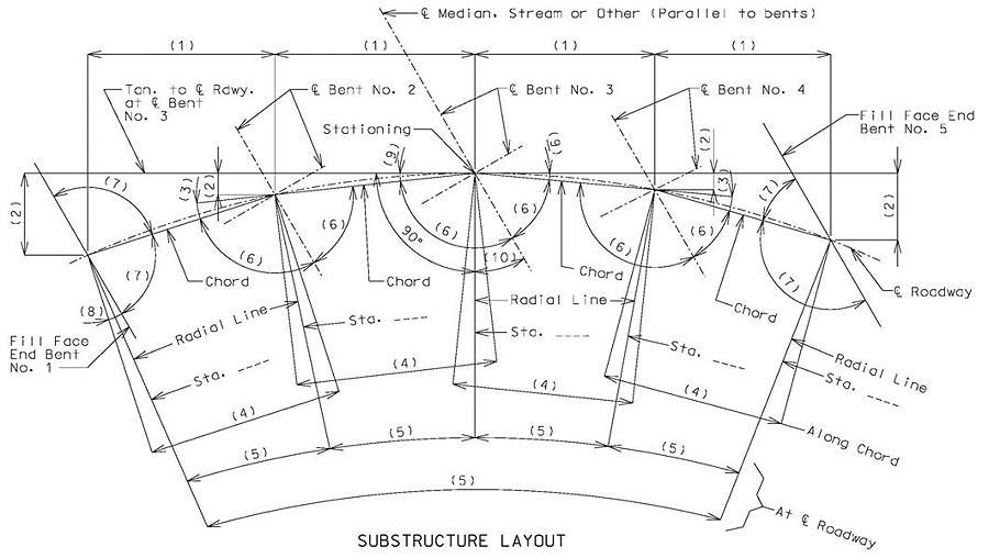
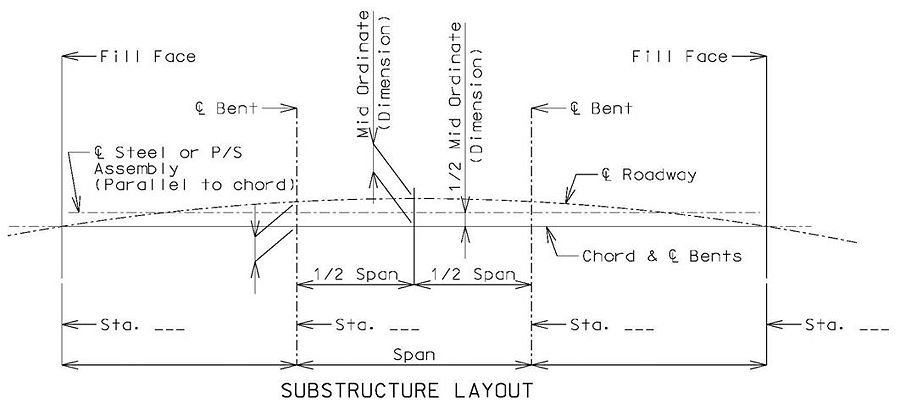
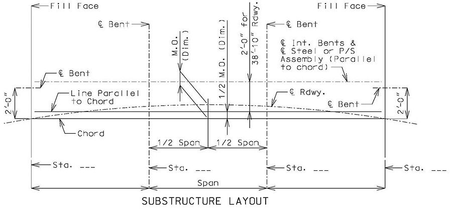
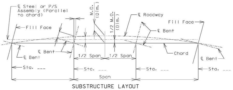
- 2.4 751.5.2.4 Substructure Layout (Curved Bridges)
- 2.1 751.5.2.1 Plan and General Elevation (Front Sheet)
- 3 751.5.3 Bridge Substructure Sheets
- 4 751.5.4 Bridge Superstructure Sheets
- 5 751.5.5 Culvert Sheets
- 6 751.5.6 Retaining Wall Sheets
- 7 751.5.7 Temporary Bridge Sheets
- 8 751.5.8 Miscellaneous Sheets
- 9 751.5.9 Miscellaneous Details
- 9.1 751.5.9.1 Joint Filler
- 9.2 751.5.9.2 Reinforcing Steel
- 9.2.1 751.5.9.2.1 Reinforcing Steel General
- 9.2.2 751.5.9.2.2 Epoxy Coated Reinforcement Requirements
- 9.2.3 751.5.9.2.3 Available Sizes
- 9.2.4 751.5.9.2.4 Length Limits
- 9.2.5 751.5.9.2.5 Spacing Limits
- 9.2.6 751.5.9.2.6 Cover Limits
- 9.2.7 751.5.9.2.7 Length Calculations
- 9.2.8 751.5.9.2.8 Development and Lap Splices
- 9.2.9 751.5.9.2.9 Mechanical Bar Splices
- 9.3 751.5.9.3 Structural Steel
751.5.1 General Detailing
751.5.1.1 Drafting Standards
| Drafting Standards Table of Contents | |||
|---|---|---|---|
| 1. CADD Levels | 2. Line Conventions | 3. Annotation | 4. Reference Notes |
| 5. Sections | 6. Hatching | 7. Breaks | 8. Surfaces |
| 9. Text Height | 10. Number Format | 11. Span Ranges | |
751.5.1.1.1 CADD Levels
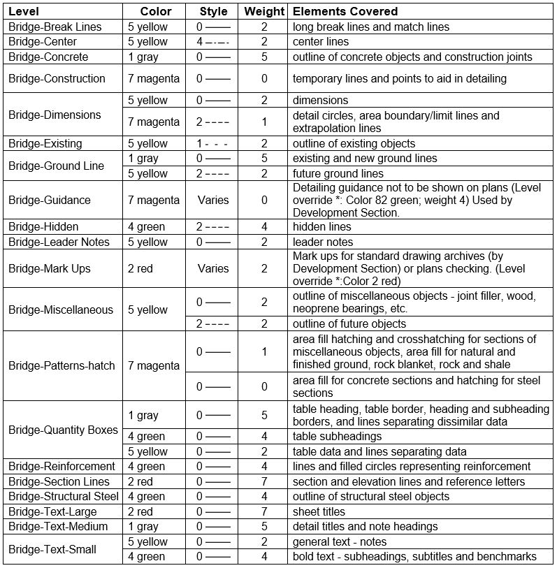
All bridge plans shall be drawn in OpenRoads Designer (ORD) and shall have the following levels, colors and line weights:
- Note: Colors represent line weights:
- Color 7 magenta = Weight 0 and 1
- Color 5 yellow = Weight 2
- Color 4 green = Weight 4
- Color 1 gray = Weight 5
- Color 2 red = Weight 7
- Color 8 brown = Weight 12 (borders)
- * Level overrides are used to print a plan sheet in black and white with some text and/or geometry printing in color. Turn on Level Overrides in View Attributes, then print the sheet in color.
- Note: Colors represent line weights:
751.5.1.1.2 Line Conventions
Reinforcing steel, except when sectioned, is shown by a single line. Centerlines are represented by a single dot between dashes. Hidden surfaces are represented by short dashed lines.
Construction joints are drawn using concrete object lines as shown.
Water surfaces will be shown by broken or dashed lines as shown. A Water Level Cell is available under CADD Standards: Front Sheets.
Patterns representing the type of ground shall be placed under ground lines. Patterns may be placed using a cell (under CADD Standards: Front Sheets), or as area fill (under CADD Standards: Area Patterns). When using area fill, turn on Drop Pattern to prevent it from placing a line around the perimeter of the pattern. The examples shown below were placed using area fill.
751.5.1.1.3 Annotation
Objects are annotated with dimensions and leader notes placed as close to the object as possible, crossing a minimum number of lines, and are to be placed outside the object whenever possible.
Dimensions of angles between two objects shall be an arc dimension drawn with the center at the point of intersection of the objects except when 90°, then right angle square may be used.
Dimension lines shall be normal to extension lines whenever possible.
If the desired text of dimension lines will not fit clearly above and below the dimension line between extension lines, the arrows shall be placed outside the extension lines with the desired text placed on one side. If it is not possible to clearly place the desired text outside the extension lines, the text may be specified using a reference note (asterisk or (1), for example) or placed away from the dimension line using a leader note with its arrow attached to the center of the dimension line.
Arrows placed inside the extension lines should have a minimum clearance of approximately one arrow length between each arrow.
The leader line of leader notes should originate from the beginning or end of the text, and the text shall be left justified.
Arrows of leader notes shall typically touch the edge of the objects they point to. When designating a structural steel member, the leg the arrow points to should be the first value mentioned in the note.
Arrows of leader notes shall point to a tilde (~) placed inside the object when the note specifies work done to the surface of the object. A cell is available for this purpose under CADD Standards: General Annotation (Tilde for Leader Notes).
751.5.1.1.4 Reference Notes
Reference notes are used when there is insufficient space to clearly designate the required information in a dimension or leader note.
A reference note consists of an indicator located in the details and, at some other location on the sheet, the note specifying the required information, preceded by the indicator.
Indicators shall either be asterisks without parentheses or numbers with parentheses. Numbers are recommended when more than three reference notes are required on a single sheet.
| * | (1) | Used for first required reference note |
| ** | (2) | Used for second required reference note |
| *** | (3) | Used for third required reference note |
| (4) | Used for fourth required reference note |
Indicators on the same sheet shall be of sequential order without any omission in the order.
If a reference note indicator is only required in one detail, the reference note shall either be placed near the indicator in the detail or directly below the title of the detail.
If a reference note indicator is used for several details that are grouped close together, the reference note shall preferably be placed near the center of the group of details.
Multiple reference notes using asterisk indicators, when listed together, shall be in sequential order with the asterisks being right justified so the text of the notes starts at the same location.
If a reference note indicator is used for several details that are not grouped close together, the reference note shall be placed with the General Notes on that sheet. The Bridge Approach Slab Standard Drawings are a good example of this case. If the General Notes are organized into subheadings, all of the reference notes shall be listed under a Reference Notes subheading.
When several reference notes are required on a sheet but the notes vary by detail, the reference notes shall be located under a Reference Notes heading separate from the General Notes and grouped by detail using subheadings. The Precast Prestressed Panel Standard Drawings are a good example of this case.
751.5.1.1.5 Sections, Elevations and Detail Circles
Sections and elevations perpendicular to the stationing are typically shown looking ahead stationing, with the exception of End Bent No.1, which is shown looking back stationing.
Sections and elevations along (parallel to) the stationing are typically shown with back stationing on the left and ahead stationing on the right.
The location of sections and elevations within other details shall be shown in those details by placing short thick lines just outside the limits of the object or at the limits of a part of the object. Where, for the sake of clarity, it is necessary to show the direction of the view taken, arrows may be used at the ends of these lines and at right angles thereto. A reference letter shall be placed at each of these lines or arrows with these same letters being used in the title of the section or elevation (SECTION A-A). A Section Arrow cell is available under CADD Standards: General Annotation, as well as in other categories where section arrows are often used.
Detail circles are used around a portion of a detailed object that needs to be shown enlarged for the sake of clarity. Detail circles shall be annotated using a leader note such as “Detail A” followed by a reference letter with this same letter being used in the title of the enlarged detail (DETAIL A).
Reference letters shall not be enclosed in quotation marks (Detail A, not Detail “A”).
For all of the sheets pertaining to the same component of the structure (all of the End Bent No. 1 sheets), reference letters for sections and elevations shall be provided in alphabetical order as occurring on the plan sheets and reference letters for detail circles shall be provided in alphabetical order as occurring on the plan sheets.
If possible, place the section detail, elevation detail or enlarged detail on the same sheet as the detail showing the location of such details. If this is not possible, place the details on another sheet, and refer to that sheet with a note, such as “Work this sheet with Sheet No. x.”; OR “For Detail A, see Sheet No. x”.
751.5.1.1.6 Hatching
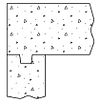
Sectional views cutting through concrete shall be hatched with the conventional dot and triangle hatching. Care shall be taken to avoid dense or crowded hatching, particularly for sections showing reinforcing steel. Use Concrete Areafill available in CADD Standards: Area Patterns, or use the Concrete Pattern Cluster cell, which is available in several categories.
Sectional views through reinforcing steel shall be shown solid. Bar size will likely need to be exaggerated for clarity. Use CADD Standard Reinforcing Steel (In Section), under Geometry.
Sectional views through structural steel shall be shown as parallel sloping line hatching. Use CADD Standard Steel Hatching, under Area Patterns. In special cases, for the sake of clarity, the sections through structural steel may be left open or shown solid.
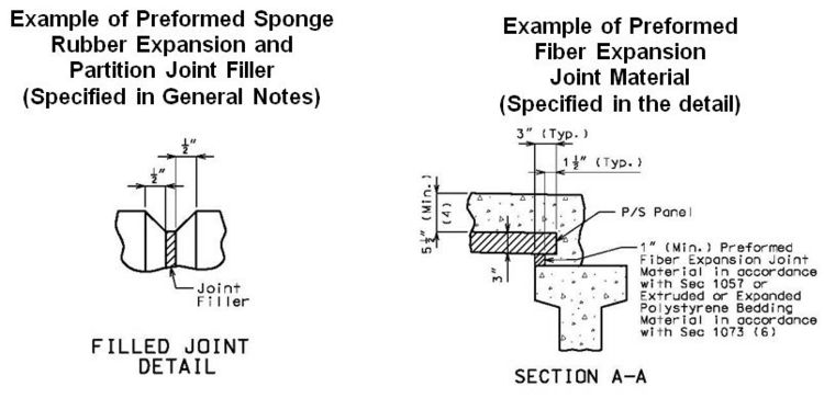
Except for special cases, all miscellaneous materials such as joint filler, castings, lead plate, etc. shall have sectional views shown hatched with light parallel lines, evenly spaced and sloped 45 degrees (preferred) to the horizontal.
751.5.1.1.7 Breaks
Breaks may be used in views for sake of clarity. “Short break” lines should be drawn without excessive waving or zigzag movements, and are drawn with the same line type as the broken object. A loop of the same line type may be used in showing breaks in round objects such as columns. “Long break” lines should be drawn as a solid line with one zig-zag near the center. Multiple zig-zags may be used for greater distances. Always use the Long Break & Match Lines CADD Standard under Geometry, NOT the same line type as the broken object.
751.5.1.1.8 Surfaces
Sloped or curved surfaces shall not be shaded except for special cases.
751.5.1.1.9 Text Height
Small text used for notes, dimensions, leader notes and tabulated data shall be 1/8 inch tall. Small bold text used for subtitles and subheadings and for bench marks shall also be 1/8 inch tall. Medium text used for titles of notes, tables and details shall be 3/16 inch tall. Large text used for sheet titles shall be 1/4 inch tall. CADD Standards: General Annotation, along with Annotation Scale, will give the correct text heights for the chosen scale.
751.5.1.1.10 Span Ranges
Bridge spans are identified by their range using parentheses and the adjacent hyphenated bent numbers. For example, Span (1-2) would define the span between the first and second bents. The order of the bent numbers correlates with the view (“Span (4-3)” if Bent 4 is on the left). Spans shall be labeled near the middle of the span directly under the overall bridge length dimension, if shown; otherwise directly under the span dimension.
In details, the text used for labeling spans shall be all capitalized Small Bold text. Regular text shall be used in notes, with only the first letter being capitalized (Span 2-3).
751.5.1.2 Weights and Measures
| Weights and Measures Table of Contents | |||
|---|---|---|---|
| 1. General | 2. Lengths | 3. Series | 4. Stationing |
| 5. Elevations | 6. Batter | 7. Slopes | 8. Temperatures |
751.5.1.2.1 General
All weights and measures shall be in English units only. Dual units shall not be used.
In notes, units shall be completely spelled out (1/2 pound, 3 inches) except in cases of very lengthy units (50 ksi, 10 cfs) and for lengths when feet and inches are both required (9’-3”).
In dimensions, leader notes and tabulated data, unit symbols shall be used if available, otherwise unit abbreviations shall be used.
When used as an adjective in a note, weights or measures shall be hyphenated with the singular form of the appropriate unit or unit abbreviations (30-pound roofing felt, 6-inch lifts).
751.5.1.2.2 Lengths
Lengths two feet or greater shall be specified in feet and inches. Lengths less than two feet shall be specified in inches. Inches shall be reported in fractions not decimals (3/4 inch, not 0.75 inch; 2 1/2 inches, not 2.5 inches) except in the bill of reinforcing steel. In notes, there is no need to report zero inches. A zero is required in front of fractions when both foot and inch unit symbols are being used. See the following for examples:
In general, lengths shall be reported to the nearest 1/8 inch. Where close work is required, lengths for metals may be reported to the nearest 1/16, 1/32 or 1/64 inch. Substructure layout for horizontally curved bridges shall be reported to the nearest 1/16 inch if necessary. Haunch, deflection and camber shall be reported to the nearest 1/16 inch for steel structures, while haunch and camber shall be reported to the nearest 1/8 inch for concrete structures. Lengths for individual legs of shaped reinforcing bars shall be reported using ¼-inch increments. Lengths of straight reinforcing bars shall be reported using one-inch increments.
In notes, an attribute such as thickness shall follow the unit of measure if required for clarification. Typically, such attributes should not be required with dimensions and leader notes since clarity is obtained through the detail. See the following for examples:
Lengths listed in a series shall be separated using lowercase “x” in lieu of “by”. In notes, the unit of measure shall be placed at the end of the series of the same units with plurality based on the last length. One exception is that units are always required preceding attributes. The length attribute when required shall be reported last. See the following for examples:
751.5.1.2.3 Series
A dimension line shall be used to designate a series of items such as reinforcing bars or piles. The dimension line shall be placed between the outside limits of the series and the series designated as follows:
| Designation of a Series of Items | ||
|---|---|---|
| Method | When to Use | Example |
| Quantity Only | small quantity clearly shown and equally distributed across the entire width of the member | 4-#7-H10 |
| Quantity and Spacing Together | exact spacing required | 5 Piles @ 5'-9" cts. |
| start and end location fixed and the actual spacing of the required quantity is slightly less than a desired spacing | 8-#6-H19 @ abt. 8" cts. | |
| start and end location fixed and the actual spacing of the required quantity is not close to a desired spacing | |__12-#6-D20__| (Equally spaced) | |
| Quantity & Spacing Separate | series has variable spacing | |__16-#5-K1 and K2__| | (Spaced as shown) | |__5 Spa. @ 6"|10 Spa. @ 8"__| |
| Spaced with Other | when items are to be placed at same location of another series of items that already have spacing designated | |__11-#5-K4__| (Spaced with K1 and K2) |
| Spaced Elsewhere | when series has already been designated in another detail, useful when multiple bar marks are involved | |__#6-U-Bars__| (Spa. as shown in Elevation) |
- A minimum of three items are required to be a series, otherwise designate using leader notes.
- Always use the symbol @ and the abbreviations cts. and abt. All other words may be abbreviated if necessary for space in accordance with Abbreviations.
- Show all reinforcement in sectional views. Show only outside bars of the series in plan and elevation views. Show all of the items for all other series (piles in a beam cap).
751.5.1.2.4 Stationing
Stations are points on the baseline at specified distances from the beginning point with 100 feet equaling one full station. All stationing should be carried to the nearest hundredth foot (1+50.14 identifies a location 150.14 feet from the beginning point of a route).
751.5.1.2.5 Elevations
Elevations shall be designated on the plans in feet, to the nearest hundredth, except as noted below.
Report to the nearest tenth of a foot for water surface elevations.
Report to the nearest foot for minimum tip penetration, pile cleanout penetration, minimum galvanized penetration and estimated maximum scour depth. (Any additional accuracy is acceptable, but not warranted.)
The foot unit is not required (Elevation 1234.98). Elevations shall be shown as close to their actual location as possible. Break lines may be used where necessary due to space limitations.
751.5.1.2.6 Batter
Batter is used to express the slight slope built into structural elements, such as piles, that are typically built vertical. Batter is reported by the horizontal component in inches per 12 inches vertically (Batter 2” per 12”).
751.5.1.2.7 Slopes
Slopes are expressed in non-dimensional ratios. The horizontal component shall always be shown first followed by the vertical component, separated by a colon. The horizontal component is unitary for slopes greater than 45 degrees and the vertical component is unitary for slopes less than 45 degrees. The components in a slope ratio must be of identical units. Slopes shall be specified “(Normal)” if perpendicular to a skewed member.
751.5.1.2.8 Temperatures
Temperatures are expressed using the Fahrenheit scale. Specific values of temperatures and ranges of temperatures shall be followed by the degree symbol and the Fahrenheit abbreviation. Temperature tolerances need only show the degree symbol (the temperature shall not be less than 40°F ±10°).
751.5.1.3 Grammar and Punctuation
| Grammar and Punctuation Table of Contents | |||
|---|---|---|---|
| 1. Abbreviations & Acronyms | 2. Symbols | 3. Capitalization | 4. Plurality |
| 5. Verb Tense | 6. Punctuation | 7. Nomenclature | |
751.5.1.3.1 Abbreviations & Acronyms
Care shall be taken to avoid the extravagant use of abbreviations.
Titles may use abbreviations only where required by lack of space.
Pay Items: The following units shall be used for pay items in quantity tables:
| cu. foot | each | linear foot | pound | sq. yard |
| cu. yard | gallon | lump sum | sq. foot | ton |
Leader Notes, Dimensions and Tabulated Data: Approved abbreviations may be used for dimensions, leader notes and tabulated data, except the abbreviated “typ.”, “min.” and “max.” shall always be used.
Notes: In general, abbreviations shall not be used in notes. Some exceptions include:
- sections of the standard specifications (Sec)
- acronyms (ASTM)
- lengthy units (psi or ksi, lb/sf)
- specific temperature (40°F)
- specific size other than reinforcement (No. 4 sieve)
- specific number (Intermediate Bent No. 2)
- where space is very limited
Abbreviations of units of measure are written without periods, with the exception of inches since it could be confused with the preposition.
Units raised to a power should be reserved for tabulated data and leader notes.
The following list of abbreviations and acronyms shall be observed where applicable. Abbreviations should be capitalized if shown that way below; otherwise capitalization shall be in accordance with Capitalization. Unless otherwise shown below, abbreviations shall always use the singular form.
| about | abt. |
| abutment | abut. |
| American Association of State Highway and Transportation Officials | AASHTO |
| angle | ang. |
| approach | appr. |
| approximately | approx. |
| approved | appv. |
| alternate or alternately | alt. |
| area | ar. |
| American Society for Testing and Materials | ASTM |
| anchor bolt | A.B. |
| April | Apr. |
| asphalt | asph. |
| August | Aug. |
| avenue | ave. |
| average | avg. |
| baluster | bal. |
| backfill | bkfl. |
| beam | bm. |
| bearing | brg. |
| beginning | beg. |
| bench mark | B.M. |
| bent | bt. |
| between | btwn. |
| bevel | bev. |
| bituminous | bit. |
| bottom | bott. |
| bracket | brkt. |
| bridge | br. (or BR, when referring to Bridge Division) |
| building | bldg. |
| cantilever | cant. |
| carbon fiber reinforced polymer | CFRP |
| cast-in-place | CIP |
| cast iron | c.i. |
| center | ctr. |
| centers (spacing, e.g. #4 @ 6” cts.) | cts. |
| Central District | CD |
| Central Office | CO |
| channel (stream) | chan. |
| clear or clearance | cl. |
| closed-ended cast in place (piles) | CECIP |
| collision (wall) | coll. |
| column | col. |
| concrete | conc. |
| concrete minimum compressive strength | f’c |
| concrete minimum compressive strength at initial loading | f’ci |
| Concrete Reinforcing Steel Institute | CRSI |
| connection | conn. |
| construction | const. |
| continuous | cont. |
| corrugated | corr. |
| counterfort | ctft. |
| countersunk | ctsk. |
| county | co. |
| creek | cr. |
| creosoted | creo. |
| cubic foot (unit of measure) | cf or ft3 |
| cubic inch (unit of measure) | cu. in. or in3 |
| cubic yard (unit of measure) | cy or yd3 |
| cubic foot per second (unit of measure) | cfs |
| culvert | culv. |
| dead load (loading) | DL |
| December | Dec. |
| deck girder | d.g. |
| degree (angular unit of measure)(temperature range unit of measure) | deg |
| department | dept. |
| design | des. |
| design flood (elevation) | D.F. |
| detail | det. |
| diagram | diag. |
| diameter | dia. |
| diameter (shown as dimension) | D. |
| ditto (steel details) | do. |
| division | div. |
| double | dbl. |
| drawing | dwg. |
| File Extension for a CADD file in ORD | .dgn |
| each | ea. |
| east | E |
| eastbound | EB |
| eastbound lane | EBL |
| elevation | elev. |
| embedment, or embedded | embed. |
| engineer | engr. |
| equal or equally | eq. |
| estimate or estimated | est. |
| excavation | exc. |
| existing | exist. |
| expansion | exp. |
| exterior | ext. |
| fabricated | fab. |
| Fahrenheit (temperature scale) | F |
| far side (steel details) | f.s. |
| February | Feb. |
| federal | fed. |
| fiber reinforced polymer | FRP |
| fill face (culvert details) | f.f. |
| fixed | fix. |
| flange | flg. |
| floor | fl. |
| foot (unit of measure) | ft |
| footing | ftg. |
| gallon (unit of measure) | gal |
| galvanize | galv. |
| gauge | ga. |
| girder | gdr. |
| glass fiber reinforced polymer | GFRP |
| grade | gr. |
| head | hd. |
| hexagonal | hex. |
| high strength (for bolts) | H.S. |
| high water (elevation) | H.W. |
| highway | hwy. |
| horizontal | horiz. |
| hour (time unit of measure) | hr |
| impact (loading) | IM |
| inch (unit of measure) | in. |
| include | incl. |
| inner diameter (shown as a dimension) | I.D. |
| interior or intermediate | int. |
| January | Jan. |
| joint | jt. |
| July | Jul. |
| June | Jun. |
| Kansas City District | KC |
| kilopound (unit of measure) | kip |
| kilopound per cubic feet (unit of measure) | kcf |
| kilopound per square feet (unit of measure) | ksf |
| kilopound per square inch (unit of measure) | ksi |
| lateral (steel details) | lat. |
| left | lt. |
| length | lgth. |
| linear or lineal (feet, inches) | lin. |
| linear foot (unit of measure) | lf |
| live load (loading) | LL |
| Load Factor Design | LFD |
| Load & Resistance Factor Design | LRFD |
| longitudinal | long. |
| low water (elevation) | L.W. |
| March | Mar. |
| maximum | max. |
| mechanical bar splice | MBS |
| median | med. |
| memorandum | memo. |
| Microcomposite Multistructural Formable Steel (high tensile strength rebar) |
MMFX |
| mile (unit of measure) | mi |
| miles per hour (unit of measure) | mph |
| minimum | min. |
| minute (angular unit of measure) (time unit of measure) | min |
| miscellaneous | misc. |
| Missouri Highway & Transportation Commission | MHTC |
| Missouri Highway & Transportation Department | MHTD (No longer used. Now MoDOT) |
| near side (steel details) | n.s. |
| nominal | nom. |
| north | N |
| northbound | NB |
| northbound lane | NBL |
| northeast (or Northeast District) | NE |
| northwest (or Northwest District) | NW |
| not applicable or not available (table data) | N/A |
| November | Nov. |
| number | no. |
| number (specific number, e.g. Sheet No. 3) | No. |
| octagonal | oct. |
| October | Oct. |
| open-ended cast in place (piles) | OECIP |
| optional | opt. |
| ordinary high water (elevation) | O.H.W. |
| ordinate | ord. |
| outer diameter (shown as a dimension) | O.D. |
| overflow | o.f. |
| overhead | o.h. |
| pair (reinforcement call out, 6 Pr. #7-U21) | pr. |
| paragraph | par. |
| perpendicular | perp. |
| piece (for partial structural shapes) | pc. |
| plate | pl. |
| point | pt. |
| polyvinyl chloride (for conduit and pipes) | PVC |
| portable document format (file extension) | |
| pound (unit of measure)(do not use #) | lb |
| pound per cubic feet (unit of measure) | pcf |
| pound per square inch (unit of measure) | psi |
| prestressed | P/S |
| profile | pr. |
| project | proj. |
| radius | rad. |
| radius (shown as a dimension) | R. |
| railroad | R.R. |
| railway | rlwy. |
| rehabilitate or rehabilitated | rehab. |
| reinforcing or reinforcement | reinf. |
| retaining (wall) | ret. |
| right | rt. |
| river | r. |
| roadway | rdwy. |
| route | rte. |
| rubber compound | rub. comp. |
| second (unit of measure) | s |
| section | sec. |
| section of MO standard and supplemental specifications | Sec |
| September | Sep. |
| shear connector | S.C. |
| sheet | sh. |
| shoulder | shldr. |
| south | S |
| southbound | SB |
| southbound lane | SBL |
| southeast (or Southeast District) | SE |
| southwest (or Southwest District) | SW |
| space(s), spacing or spaced | spa. |
| specification | spec. |
| square | sq. |
| square foot (unit of measure) | sf or ft2 |
| square inch (unit of measure) | sq in. or in2 |
| square mile (unit of measure) | sq mi or mi2 |
| square yard (unit of measure) | sy or yd2 |
| standard | std. |
| station | sta. |
| stay-in-place | SIP |
| steel minimum yield strength | fy |
| St. Louis District | SL |
| stream face (culvert details) | s.f. |
| street | st. |
| stringer | str. |
| structural | struc. |
| structural liaison engineer (consultants’ contact person) | SLE |
| structural project manager | SPM |
| substructure | substr. |
| superelevation | s.e. |
| superstructure | superstr. |
| symmetrical | symm. |
| tangent | tan. |
| through | thru |
| thread | thd. |
| transportation project manager (at district) | TPM |
| transverse | trans. |
| truss | tr. |
| typical | typ. |
| use in place | U.I.P. |
| variable | var. |
| vertical | vert. |
| vertical curve (length in curve data) | V.C. |
| vertical point of intersection (curve data) | VPI |
| weight | wt. |
| welded wire reinforcement | WWR |
| west | W |
| westbound | WB |
| westbound lane | WBL |
| widen or widening | wid. |
| with | w/ |
| without | w/o |
| wrought iron | w.i. |
| yard (unit of measure) | yd |
| year (unit of measure) | yr |
751.5.1.3.2 Symbols
In general, symbols shall not be used in notes. Some exceptions include:
- the # symbol when calling out bar sizes (#4)
- measurements with both feet and inches (2’-0¾”)
- where space is very limited
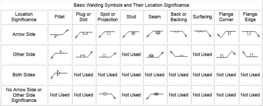
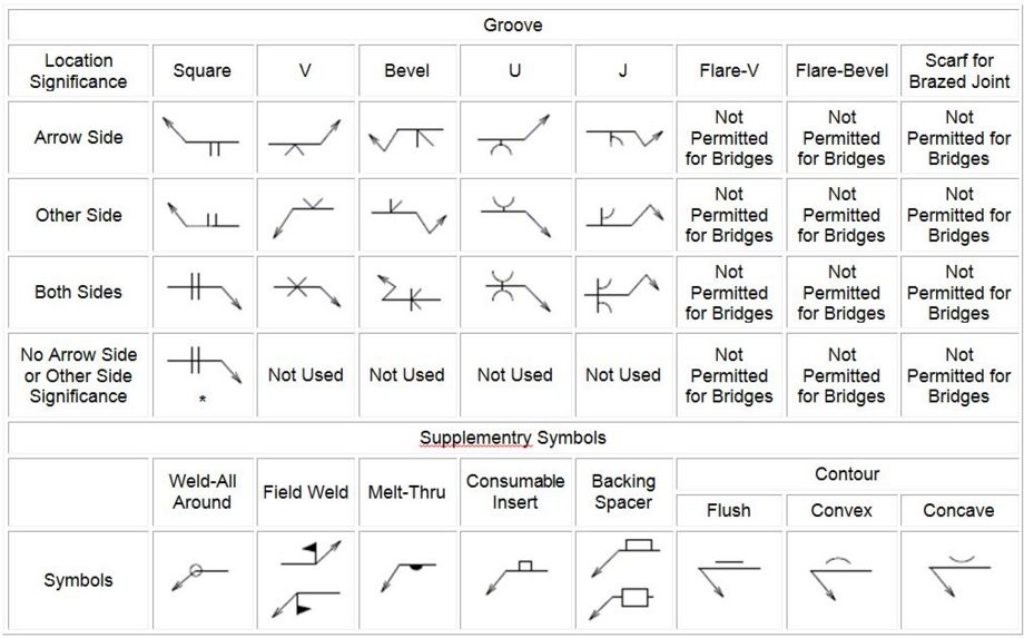
Symbols shall be used in dimensions, leader notes and tabulated data for noting reinforcing bars, structural steel shapes, bolts, welding, lengths, angles, etc. Unit symbols shall not be omitted where they apply, except in authorized designation of structural steel shapes, e.g. HP10x42.
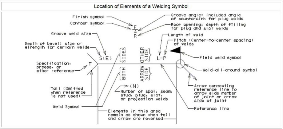
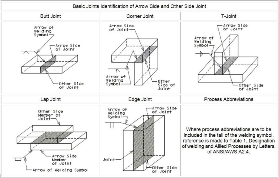
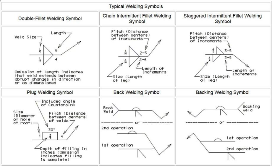
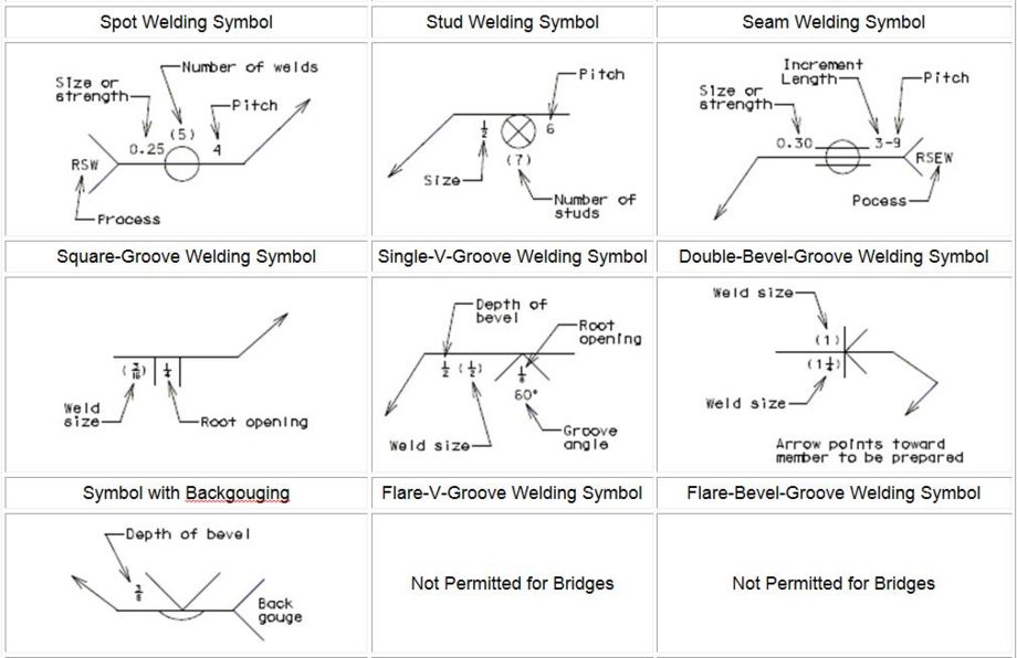
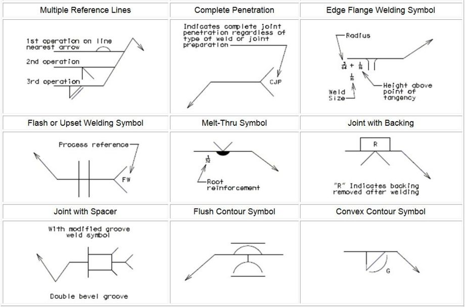
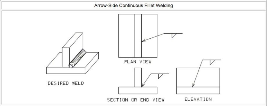
The following list of approved symbols shall be observed where applicable and are shown with the required spacing. Welding symbols are not shown below but shall be in accordance with American Welding Society (AWS) and with EPG 751.5.9.3.1 Welding.
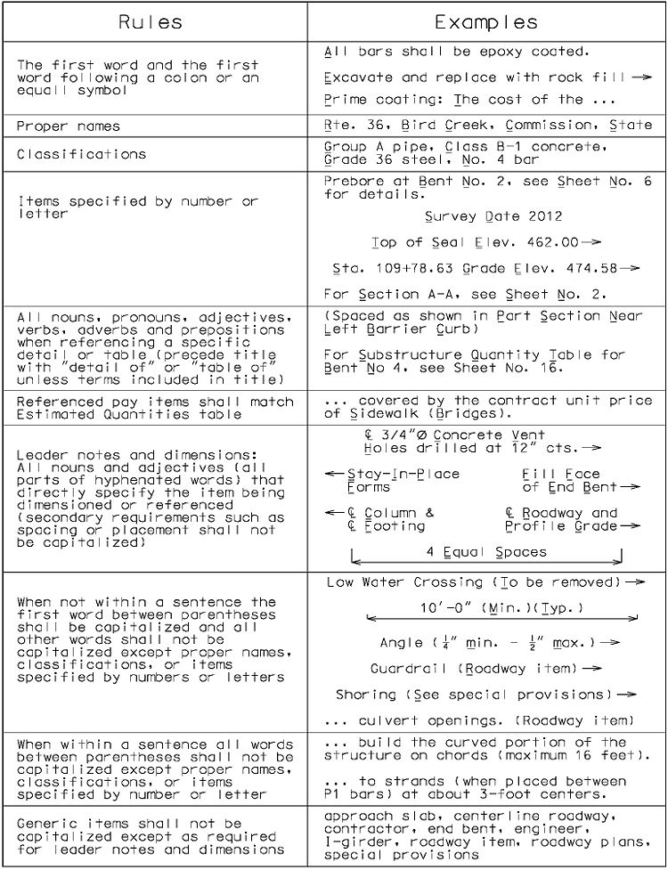
751.5.1.3.3 Capitalization
The following capitalization rules shall be used except notes for design specifications, loadings and unit stresses shall match as shown in EPG 751.50, A1. Design Specifications, Loadings & Unit Stresses and Standard Plans.
Titles and subtitles of details and sheet titles shall be in all capitals, including bracketed information, except for units of measure, e.g. PART SECTION (TYPICAL).
Titles, subtitles and headings of notes and tables and items in tables (except for quantity tables) shall have all nouns, pronouns, adjectives, verbs, adverbs and prepositions capitalized except for units of measure. The capitalization of the pay items in quantity tables shall be in accordance with EPG 751.6 General Quantities.
Units of measurement shall always be lowercase except for Fahrenheit (F).
751.5.1.3.4 Plurality
The following words are typically used as noncount nouns in singular form. When these words describe a quantity of items then the item shall be made plural, e.g., two material samples shall be taken or three pipe units shall be tested.
| Noncount Nouns |
|---|
| guardrail |
| material (Exception: Materials Division) |
| pile |
| pipe |
For consistency, when referring to a group of items, the name is pluralized and not the indicator. See the examples below.
| Correct | Incorrect |
|---|---|
| Sheets No. 1, 2 & 3 | Sheet Nos. 1, 2 & 3 |
| Walls No. 1, 2 & 3 | Wall Nos. 1, 2 & 3 |
| Bents No. 1, 2 & 3 | Bent Nos. 1, 2 & 3 |
When dimensions and quantities of items are used as hyphenated adjectives (describing another object) the dimension unit or the item shall always be in singular form.
| Examples |
|---|
| 4-inch hole |
| Three-strand cable |
751.5.1.3.5 Verb Tense
Past tense shall be used for required work on the plans as if already completed, e.g., STAGED CONSTRUCTION as a title, not STAGE CONSTRUCTION.
Past tense shall also be used with verbs used as adjectives, including words describing the orientation of structures or structural components, e.g. prestressed girders or squared end precast panels.
Present tense shall be used for all instructions, e.g., Remove timber header when concrete pavement is placed, see end bent sheets for details.
751.5.1.3.6 Punctuation
General
Notes shall be written using complete punctuated sentences. Sentence fragments of explanatory or qualifying remarks marked off by parentheses may be inserted into completed punctuated sentences.
Leader notes and dimensions shall consist of sentence fragments. Sentence fragments are never punctuated. Use parentheses to divide separate multiple fragments, e.g., #4 Bars under bearing (6” Maximum spacing of stirrups).
Quotation Marks
Quotation marks shall only be used in instructions to quote the exact words that are to be written by the contractor, e.g. the word “RECOATED” shall be painted on the structure. Quotation marks shall not be used for emphasis and around specific items such as titles of tabulated data, pay items or section letters.
Hyphens
Hyphens, without spaces before or after the hyphen, shall be used to link two or more words or elements that act as a single idea. The following rules shall be followed.
- Compound Adjectives Before a Noun
- Examples: cast-in-place slab, 72-hour-old concrete.
- But not for: slab is cast in place, concrete is 72 hours old.
- Examples: I-girder bridge, H-pile footing, R-bar shape
- But not for: I girders shall be…, H pile are used…, R bar shall be…
- Examples: 1/4-inch joint, one-fourth-inch joint
- But not for: joint is 1/4 inch, joint is one-fourth inch.
- Examples: 3/4-inch joint, three-fourth-inch joint
- But not for: joint is 3/4 inch, joint is three-fourths inch.
- Examples: 1 1/2-inch pipe, one-and-one-half-inch pipe.
- But not for: pipe is 1 1/2 inches, pipe is one and one-half inches.
- Examples: one-strand cable, three-strand cable, lot-by-lot basis, chain-link fence, hot-mix asphalt.
- Examples: cast-in-place slab, 72-hour-old concrete.
- Compound Numbers 21-99
- Example: Twenty-two feet
- Verbs Using Compound Nouns
- Examples: water-proof surfaces, hydro-demolition deck
- Fractions (Spelled Out)
- Examples: One and five-eighths, One-third of slab
- Prefixes and Suffixes
- Before Proper Nouns or Adjectives
- Example: mid-July
- But not: midpoint
- Example: mid-July
- Before Proper Nouns or Adjectives
- Between Duplicated Vowels
- Examples: re-established, pre-existing, semi-invalid
- But not: subbase, prestressed
- Examples: re-established, pre-existing, semi-invalid
- Between Duplicated Vowels
- Avoiding Confusion
- De- (e.g., de-icing)
- But not: defrost
- Co- (e.g., co-pilot)
- De- (e.g., de-icing)
- Avoiding Confusion
- Always With
- Self- (e.g., self-propelled)
- -free (e.g., tack-free)
- -based (e.g., water-based)
- Always With
- Reinforcement Callouts
- In Bar Marks Between the Bar Size and Bar Designation
- Example: #4-H100 (dimensions, leader notes & notes)
- Between Number Required and the Bar Mark
- Examples: 6-#4-H100 (dimensions & leader notes)
- Six #4-H100 bars (notes)
- Examples: 6-#4-H100 (dimensions & leader notes)
- Between Pairs Required (Pr.) and the Bar Mark
- Examples: Pr.-#4-H100 (dimensions & leader notes)
- Pair of #4-H100 bars (notes)
- Examples: Pr.-#4-H100 (dimensions & leader notes)
- Not Between Number Required and Pairs (Pr.)
- Examples: 4 Pr.-#4-H100 (dimensions & leader notes)
- Four pairs of #4-H100 bars (notes)
- Examples: 4 Pr.-#4-H100 (dimensions & leader notes)
- In Bar Marks Between the Bar Size and Bar Designation
751.5.1.3.7 Nomenclature
In addition to that found in Sec 100, the following engineering terminology, when required, shall be used on bridge plans. This list is not meant to be all inclusive, but primarily contains terminology unique to MoDOT.
| Terminology | Application |
|---|---|
| beam | In general any horizontal supporting member however the term is specifically applied to the following superstructure members: steel wide flange members, and precast concrete box, precast voided slab and precast solid slab members. |
| blockout | A one word noun used for voids formed into structural elements for a particular application (expansion device blockout, flange blockout) or used for a structural element placed in the void formed into another element (curb blockout). |
| block out | A verb used for the process of forming a void into a structural element (The contractor shall block out the end of the top flange to accommodate the placement of diaphragm reinforcement.) |
| complete in place | This phrase is used to cover all work and material required to complete a particular task or construct a particular item. Hyphens are not used and the phrase is usually set apart from the rest of the sentence with commas (Concrete masonry, complete in place, will be paid for…). |
| deck | The portion of the superstructure that supports the live load |
| girder | Large longitudinal superstructure members specifically applied to the following: steel plate girders, precast concrete I, precast bulb-tee, precast double-tee and precast NU members, and any cast-in-place concrete member. |
| guardrail | Roadway traffic barrier consisting of heavy-gauge rolled steel beams mounted on strong posts. It is used to protect traffic from roadside obstacles or to prohibit traffic movements. |
| option | A noun used for one of the choices which can be made. |
| optional | An adjective used for not compulsory; left to personal choice; elective. |
| saw cut | A noun or adjective used for joints cut into structural elements for a particular application (Silicone shall be placed in the saw cut) (The saw cut joint shall…). A verb used for the process of cutting a joint into a structural element (The contractor shall saw cut the barrier to the depth shown on plans.) |
| slab | Flat structural member usually formed of a single piece and can transfer loads horizontally to supporting members (slab on beam) or vertically to a supporting base material (slab on grade). |
751.5.1.3.8 Numbers
In notes, the numbers zero and one shall always be spelled out (one inch, zero degrees) while all numbers shall be spelled out if at the start of a sentence (Two feet is the minimum distance…).
In notes, the numerals 2 through 10 shall be used for specific numbered items or if followed by a unit of measure otherwise spell out the number (Bent No. 4, 2 feet, 9 miles, six bolts, eight bars). In dimensions, tabulated data and leader notes; the numerals 2 through 10 shall be used even with quantity of items (6 bolts, 8 bars).
Numerals shall be used for all numbers in excess of ten (11 feet, 14 books, 26 miles, 12 sections) except for numerals beginning a sentence of a note (Twelve posts shall…).
Commas shall be used for numbers 10,000 and greater, for example 14,000 versus 9642.
Periods shall be used for the decimal marker of decimal numbers and preceded by zero for numbers less than one (0.254).
Fractions used in dimensions, tabulated data and single-lined leader notes shall be written with undersized text using a vinculum separating the numerator from the denominator and immediately follow whole numbers ("), except for rare cases where lack of vertical space makes this impractical (also known as “stacked” fractions).
Fractions used in notes and multiple-lined leader notes shall be written with regular text using a forward slash separating the numerator from the denominator and separated from whole numbers by a space (1 1/2).
Where multiple numbers are needed in a note, use commas or reword to avoid confusion (Instead of “Use 36 0.6”Ø Grade 270 strands with…”, say “Use 36 strands, 0.6”Ø Grade 270, with…”); or spell out one or more of the numbers (Two 1 1/2-inch diameter bolts).
751.5.1.4 Contract Plan File Name Convention
The file naming convention for all Bridge contract plans shall be: B_[bridge#]_[sheet#]_[job#]_[optional description].dgn. (Example: B_A8690_004_J3S2219_BENT1.dgn)
- B for Bridge.
- [bridge number] (e.g. A8690).
- [sheet#] is the number of a particular sheet unique to a bridge number (e.g. 004).
- [job#] is the job number assigned to the project (e.g. J3S2219).
- [optional description] is an abbreviated description of the sheet information (e.g. BENT1, DRAINvert, BCelev, SLABplan ).
NO spaces or special characters shall be used in the filename. Acceptable characters are letters, numbers, underscores or dashes.
751.5.1.5 Order of Plan Sheets
The following table provides the preferred order of plan sheets for most new girder and beam bridges or the widening of girder and beam bridges.
| Type of Sheet | General Name of Sheet | Comments |
|---|---|---|
| Location and Layout | Plan and General Elevation (Front Sheet) | 1 Required with curved bridges. |
| Estimated Quantities and General Notes | ||
| Staged Construction | ||
| Substructure Layout 1 | ||
| Substructure | CIP Piles | |
| First End Bent | ||
| Vertical Drain at End Bents | ||
| Intermediate Bents | ||
| Last End Bent | ||
| Bearings and Girder/Beam Chairs | ||
| Superstructure: Concrete Girders and Beams |
Girder Layout1 & 2 | 2Steel intermediate diaphragm details may be added to this sheet if space allows. 3 For NU Girders, WWR sheet comes before the Bars sheet. 4 Required with an expansion device at the end bent. |
| Prestressed Girders or Beams3 | ||
| Steel Intermediate Diaphragms | ||
| End Diaphragm at First End Bent 4 | ||
| Diaphragms at Intermediate Bents | ||
| End Diaphragm at Last Bent 4 | ||
| Superstructure: Steel Girders and Beams 5 |
Plan of Structural Steel | 5 For simpler bridges, the sheets shown may be details that are combined on sheets titled “Steel Plate Girders” or “Steel Wide Flange Beams” |
| Elevation of Girder/Beam | ||
| Girder/Beam Curve Offsets 1 | ||
| Camber and Dead Load Deflection | ||
| Splices | ||
| Diaphragms, Crossframes and Stiffeners | ||
| Superstructure: Bridge Decks |
Precast Prestressed Panels | 6 Camber refers to the P/S camber diagram and is only required for concrete members. Haunching refers to the diagram for concrete members and to the detail for steel members. Slab Elevations refer to the theoretical bottom of slab elevation table. Often the haunching and slab elevations for steel members are shown on the same sheet with camber and dead deflection diagrams for simpler bridges. |
| Slab Drains | ||
| Expansion Devices | ||
| Camber, Haunching and Slab Elevations6 | ||
| Plan of Slab Showing Reinforcement | ||
| Section Thru Slab | ||
| Slab Pouring Sequence | ||
| Slab Curve Ordinates1 | ||
| Superstructure: Barrier or Railing |
Elevation Sheet | |
| Barrier or Railing Details at End Bents | ||
| Median Barrier Details | ||
| Miscellaneous Sheets | Approach Slab | |
| Bill of Reinforcing Steel | ||
| Sign Attachments | ||
| As-Built Pile and/or Drilled Shaft Data | ||
| Boring Data |
For simpler bridges some of the above sheets may be combined, for example the section thru slab and slab pouring sequence are often on the same sheet. At the discretion of the Structural Project Manager identical end bents can both use the details of the first end bent with the number of the last end bent being added to the sheet title. Also at the discretion of the Structural Project Manager identical or similar intermediate bents can use the same details adding tables for variable dimensions.
For large or complex structures with a large amount of details an Index Sheet is often added as the front sheet. The Location Sketch, Land Survey Block, and the Structural Title Block typically located on the Plan and General Elevation Sheet is located with the Index of Drawings on the Index Sheet.
751.5.1.6 Example Bridge Plan Sheets
The following contains example bridge plan sheets with commentary:
| Example Bridge Plans |
|---|
| Typical Prestressed Concrete Tangent Bridge |
| Alternate Sheets for Steel Bridges |
| Additional Sheets for Curved Bridges |
751.5.1.7 Contract Addendums and Construction Changes
Contract Addendums:
- All contract addendums are new documents/plan sheets
- Central Office Design Division controls contract addendum releases and sequential ordering.
A bid revision (contract addendum) will be required if any of the contract documents require revisions after the project has been advertised but before the letting. The revisions shall be made in accordance with EPG 103.1.6.6.1.1.Revisions to Plans Sheets while maintaining the existing information. The file names of the revised plan sheets shall be in accordance with EPG 103.1.6.6.1.2 File Naming Convention for Plan Sheet Changes. It is important that revision numbers used in the file names of the revised sheets saved to the appropriate contract plans folder in ProjectWise correspond to the number of the contract addendum in coordination with Central Office Design Division Bidding and Contract Services. The new files shall be processed in accordance with EPG 237.9.4 File Naming Convention for Addendums.
Construction Changes:
- Construction changes may be new plan sheets or revised plan sheets.
- Bridge Division controls construction change releases and sequential ordering.
- Sequential ordering for multiple structures in a project is relative to each structure.
A bridge change order (construction change) will be required if the final contract bridge plans require revisions after the project has been awarded. Similar to contract addendums, change order revisions shall be made while maintaining the existing information.
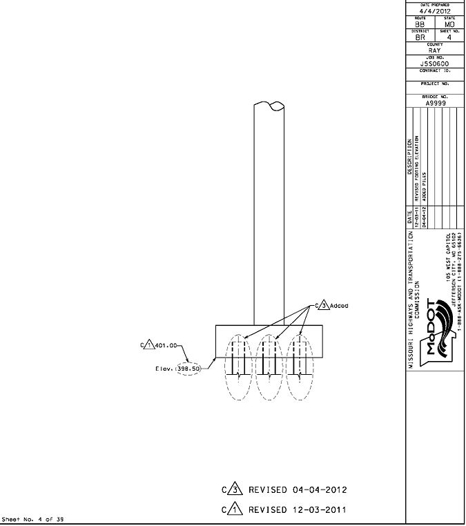
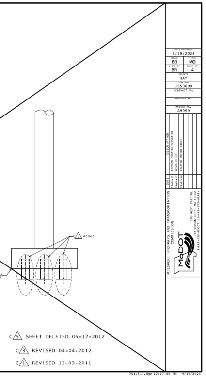
Revisions shall be identified with leader notes with a “C” prior to a sequential bridge change order number (not project) circumscribed by a triangle. For example, all revisions for the first bridge change order shall be identified with a “1” in the triangle, all revisions for the second bridge change order with a “2” in the triangle, etc. Following the triangle should be one of the following:
- “Added” ← for identifying new details being added
- “Deleted” ← for identifying existing details being deleted
- New values replacing existing values
The overall revision to the sheet shall also be noted near the lower right side of the sheet using the same “C” and triangle format as used with the individual revisions made on the sheet. Following the triangle should be one of the following:
- “Revised (Date)” ← for existing sheets with revisions being added
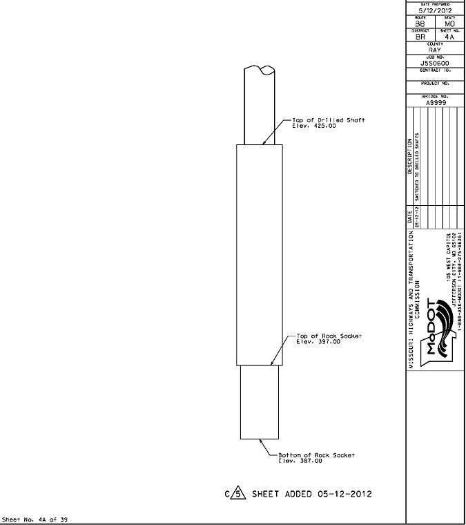
- “Sheet Added (Date)” ← for new sheets being added
- “Sheet Deleted (Date)” ← for existing sheets being deleted
The file name for all revised sheets for the first bridge change order shall contain a _C001 at the end of the final contract plan file name; the second bridge change order shall contain a _C002; etc. The signed and sealed revised plan sheets shall be saved to the appropriate contract plans folder in ProjectWise. The following example shows the progression of file names for plan sheets during bidding and construction.
| Progression of File Names During Bidding and Construction |
|---|
The signed and sealed change order plan sheets shall be printed to pdf, combined into a single file and saved in the appropriate eProjects location. The Structural Project Manager shall send a link to this file via email to the Resident Engineer and copied to others for processing. A change order template for Outlook is available in Development_Forms.
| Examples | |
|---|---|
| Revising Existing Sheets | |
| When minor change order revisions can be made clearly to existing sheets, items revised, added or deleted are enclosed using the Detail Circle line type. The overall revision to the sheet is noted near the lower right side of the sheet. The date and description of the revision may also be added to the final plans title block (optional). | |
| Deleting Existing Sheets | |
| When details on a sheet are no longer applicable, or change order revisions are too complicated to be made clearly, the entire sheet is crossed out with a bold line (match border). The deletion is noted near the lower right side of the sheet The date and description of the revision may also be added to the final plans title block (optional). | |
| Adding New Sheets | |
| When a new sheet is needed to replace a deleted sheet or to add additional change order details, the addition is noted near the lower right side of the sheet. The date and description of the revision may also be added to the final plans title block (optional). | |
751.5.2 Location and Layout Sheets
751.5.2.1 Plan and General Elevation (Front Sheet)
Typically, the first sheet of bridge plans for new structures and the widening or extension of existing structures shows a Plan Detail, a General Elevation Detail and several information blocks. For the rehabilitation of existing bridges a Typical Section Thru Deck Detail is shown instead of the Plan and General Elevation. There are also several supplementary details, dependent on the type of structure that may be required. This subarticle provides detailing guidelines for these items.
| Front Sheet Table of Contents | ||||
|---|---|---|---|---|
| 1. Plan Detail | 2. General Elevation Detail | 3. Information Blocks | 4. Typical Section Thru Existing Deck Detail | 5. Supplementary Details |
| 1.1 Substructure Elements | 2.1 General Elevation View | 3.1 Structure Description | 5.1 Location Sketch | |
| 1.2 Skew Detail | 2.2 Elevations | 3.2 Land Survey | 5.2 Foundation Data | |
| 1.3 Boring Locations | 2.3 End of Slab | 3.3 Final Plans Title | 5.3 Hydraulic Data | |
| 1.4 Bridge Roadway Width | 2.4 Bent Number & Fixity | 3.4 Standard Plans | ||
| 1.5 Features Crossed | 2.5 Vertical Alignment Data | 3.5 Bench Mark | ||
| 1.6 North Arrow & Curve Data | 2.6 Ground Lines | 3.6 Structural Title | ||
| 1.7 Miscellaneous Notes | 2.7 Features Crossed | |||
| 1.8 Miscellaneous Details | 2.8 Slope Protection | |||
| 2.9 Miscellaneous Notes | ||||
| 2.10 Miscellaneous Details | ||||
751.5.2.1.1 Plan Detail
The following items shall be included in or near the Plan Detail.
751.5.2.1.1.1 Substructure Elements
For new bridges or the widening of existing bridges the following substructure elements shall be drawn to scale and shown in the Plan Detail.
| Beam Caps1 | Detached Wings | Rock Sockets |
| Collision Walls | Drilled Shafts | Seal Courses |
| Columns | Footings | Tie Beams |
| Deadman Anchors | Piles2 | Webs |
- 1 Incidental details, such as steps, keyways, and anchor bolts (at the top of beams) shall not be shown.
- 2 Sway bracing shall not be shown at intermediate pile cap bents. Battered piles need only be shown for a short distance past the edge of the bent ending with a long break line.
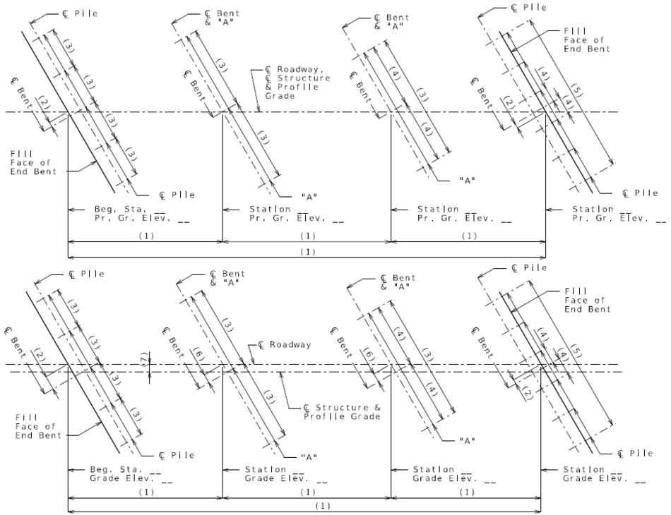
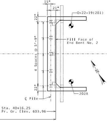
The substructure shall be labeled and dimensioned as shown below. The first drawing specifies roadway elevations as profile grade elevations, since the profile grade is located at the centerline of roadway. On the second drawing, these elevations are specified as grade elevations. The second figure also shows the additional dimension required at the intermediate bents when the centerline of the roadway does not pass through the geometric center of the intermediate bents. This occurs with all unsymmetrical roadways and occasionally symmetrical roadways with horizontally curved continuous prestressed bridges. These drawings are applicable to both tangent and horizontally curved bridges.
For dual roadways/divided highways, the centerline of median shall be shown and specified and the perpendicular or radial offset from centerline of roadway shall be dimensioned.
For tangent, squared structures, the transverse centerline of the bents line up with the centerline of the structure, and therefore the centerline of bent can be added to the centerline of structure’s leader note.
When the profile grade is not along the centerline of roadway, but is along either the centerline of structure or median, the profile grade shall be added to the appropriate leader note. When the profile grade is not along the centerline of roadway, structure or median, the location of profile grade shall be shown in the roadway width detail in accordance with Roadway Width.
The span lengths for steel and prestressed bridges given in the Bridge Memorandum or Design Layout are horizontal dimensions. For prestressed girder or beam sheets, the actual girder or beam length shall be adjusted accordingly for grade.
The following additional dimensions shall also be shown in the plan detail:
| Length and width of footings and seal courses |
| Perpendicular distance from centerline of piles to the front face and to the fill face of end bents |
751.5.2.1.1.2 Skew Detail
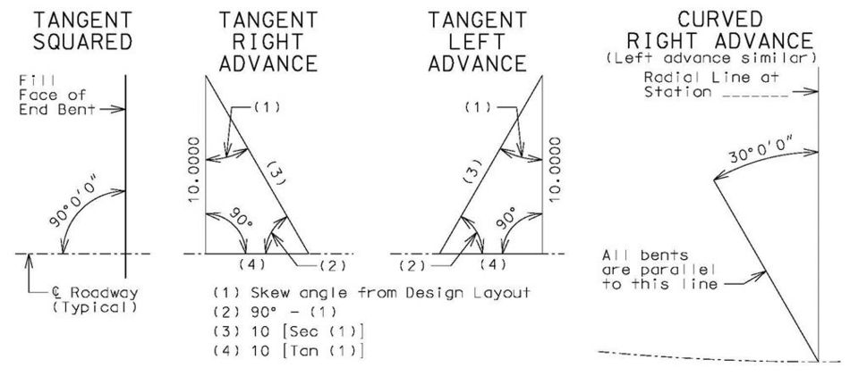
The following skew detail shall be drawn off the centerline of roadway (right angle square can also be used instead of 90° angle dimension):
For curved bridges where the referenced radial line occurs at a congested location, and it is not possible to show the skew detail clearly, state the skew requirements by providing the following note:
- For Skewed Bents:
- All bents are parallel to a line skewed __ right left advanced from a radial line at station __.
- For Squared Bents:
- All bents are parallel to a radial line at station __.
751.5.2.1.1.3 Boring Locations
All available boring data locations shall be shown with the boring symbol (Boring Symbol cell, under CADD Standards: Front Sheets)
Each boring location shall be labeled with its identifying number.
Add Notice and Disclaimer Regarding Boring Log Data near the Plan detail. This note is available as a cell in CADD Standards: Detailing Notes (E3.2 Notice and Disclaimer).
If inadequate space is available for placement of the disclaimer note, place the portion that says “Indicates location of borings.” (including the symbol), and place the rest of the note on the General Notes and Estimated Quantities Sheet. Add a note nearby stating, “For Notice and Disclaimer Regarding Boring Log Data, see Sheet No. _.”
751.5.2.1.1.4 Bridge Roadway Width
A small portion of the outside edges of the bridge roadway shall be shown at the proper location within one of the spans if space allows, but may be placed adjacent to bridge if required for clarity. The dimension of the overall roadway width shall be provided, followed by “Roadway”. The dimensions from the centerline of roadway to each edge of the roadway shall be provided also. If the profile grade is not along the centerline of roadway, structure or median, a small portion of the profile grade shall also be shown, and the offset dimension from the centerline of roadway provided. The dimensions need not be specified as radial for curved structures.
See the Bridge Memorandum for location of the profile grade. Generally, the profile grade will be shown in the cross section through the superstructure on the slab sheet and in the plan view on the front sheet of the design plans. Generally, the profile grade is at the centerline of roadway for two-way traffic bridges. For one-way traffic bridges used in standard divided highways, the profile grade is at some other location away from the centerline of roadway. When the profile grade is not located along the centerline of the roadway, the centerline of roadway elevations shall be specified as grade elevations.
751.5.2.1.1.5 Features Crossed
Centerlines of Features Crossed
The centerline of existing, new and future roadways, railroads and trails (if known) shall be shown at their proper location, extended slightly past the boundary of the bridge. The intersection of a centerline with the bridge’s centerline shall be specified as follows.
The centerline of dual lane roadways shall also be shown and specified with the appropriate lane designation.
Boundary and Clearances of Features Crossed
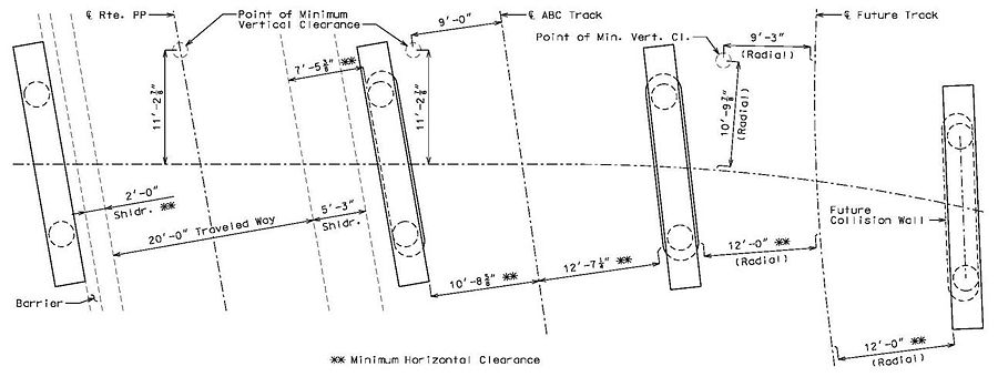
Using boundary lines (style 2, weight 1) the edge of travel lanes, shoulders and barrier of roadways and the edges of trails shall be shown at their proper location, extended slightly past the boundary of the bridge. The travel lanes and shoulders shall be dimensioned and labeled as shown in the following detail. The barrier shall be labeled as well.
The minimum horizontal clearance to the closest substructure element, wall element, rigid barrier, or to the toe of slope steeper than 3 to 1 (1V:3H) on each side of each roadway and railroad underneath a bridge shall be dimensioned at their proper location and labeled as shown in the following detail. Barrier or railing, beam caps, wall coping, and collision walls will control over columns and retaining walls. The horizontal clearance shall be measured from the edge of traveled way for roadways (clearance includes shoulders and auxiliary lanes) and from the centerline of tracks for railroads.
Using detail circles (style 2, weight 1) the point of minimum vertical clearance for each existing, new and future roadway and railroad shall be shown at their proper location obtained from the design. Each point of minimum vertical clearance shall be dimensioned from the intersecting centerlines (unless on centerline) and also labeled as shown in the following detail.
751.5.2.1.1.6 North Arrow and Curve Data
When the Location Sketch is eliminated, or placed on the General Notes and Estimated Quantities Sheet, the north arrow and all horizontal curve data of roadways going over, under, or within 150 feet of the structure shall be provided near the Plan Detail.
751.5.2.1.1.7 Miscellaneous Notes for the Plan Detail
Applicable notes of EPG 751.50 E3. Miscellaneous notes shall be placed near the Plan Detail.
751.5.2.1.1.8 Miscellaneous Details for the Plan Detail
- Bridge spans, identified in accordance with Span Ranges.
- Outline of existing substructure components when they are in close proximity to new substructure.
- Temporary shoring required for construction and specified as a roadway item, if applicable.
- For staged bridge construction with MSE walls at the abutments, consider specifying temporary MSE walls on the plan details. Sometimes due to limited space or to retain improved foundation material or to retain existing slope contractor may need to provide temporary shoring prior to constructing temporary MSE wall systems in staged construction, but only the temporary MSE wall should be indicated on the plans.
- MSE walls built in conjunction with bridge shall be shown with the wall number specified. Walls need only be shown for a short distance past the boundary of the bridge ending with a long break line.
- Alignment of new or existing underground utilities that may cause construction difficulties due to the close proximity to new substructure.
751.5.2.1.2 General Elevation Detail
The following elements need to be included in or near the General Elevation Detail.
751.5.2.1.2.1 General Elevation View
The general elevation view of a structure is to show the structure in its entirety meaning that, for a bridge, this would include the superstructure, substructure and foundations. Because of limited space on a plan sheet and scalability conflicts, for example in the case of a bridge where a bridge is much longer than tall, controlling the amount of distortion becomes critical. Because of this, the information shown should be depicted as proportionally correct as is possible but in all cases the relational distinctions made should be rational such as correctly showing both the elevation and drawing of the bottom of a drilled shaft as it relates to other details.
The elevation of the structure shall be drawn as a section through centerline of the structure but showing the side elevation of the end bent wing walls and barrier or railing. Only one column will be shown (no isometric views of the structure). The bents in the general elevation detail shall line up with the span length extension lines in the plan detail. The vertical placement of structural elements shall be shown as close to their actual location as possible. Long piles need only be shown for a short distance below footings ending with a long break line.
These hidden items shall be shown: end of slab, fill face, approach notch, wing brace, collision walls, tie beams, web beams, pile webs and piles embedded in concrete or inside spacers. For clarity, girders embedded in diaphragms should not be shown.
751.5.2.1.2.2 Elevations
The elevations of the bottom of the following items shall be specified: rock sockets, web beams, sway bracing, spread footings and pile footings. Add “(Not above)” if indicated in the Bridge Memorandum or Design Layout. The elevation of the bottom of footing need not be specified when a seal course is present.
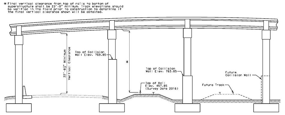
The elevations of the top of the following items shall be specified: seal course, anticipated sound rock, drilled shafts, permanent casing, tie beams, collision walls and rails of railroads at location of minimum vertical clearance. Add “(Survey Date ___)” to the rail elevation, using the date reported in the bridge survey report.
For water crossings, the design flood elevation and low water elevation (ordinary water elevation if low water not available) shall be specified by pointing to the top of a water line symbol placed at the proper vertical location, preferably within the main span of the bridge. A single line may be used to represent the low water elevation if there is not enough room to clearly show a water line symbol. The low water elevation shall not be shown or specified if the stream runs dry.
The excavation datum elevation, if required shall be specified by pointing to a single line placed at the proper vertical location, preferably below the ground line, near an intermediate bent. The excavation datum shall not be specified when no excavation exists below that elevation, such as in the case of all intermediate bents being pile cap bents or drilled shafts.
751.5.2.1.2.3 End of Slab
The end of slab at both ends shall be called out with the following leader note:
751.5.2.1.2.4 Bent Number and Fixity
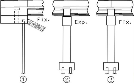
The bent number and bent fixity shall be specified for all bents as shown to the right. The text for both shall be the regular small text used for all notes. “Fix.” shall be used for all integral bents and non-integral bents with fixed bearings. “Exp.” shall be used for all bents with expansion bearings. “F.” and “E.” may be used if required due to lack of space.
751.5.2.1.2.5 Vertical Alignment Data
The vertical alignment of bridges shall be placed directly above the bridge in the General Elevation Detail, with vertical curve data placed as near as possible to the vertical point of intersection.
A crest vertical curve detail is shown. If the bridge is located on a sag vertical curve, the detail for a sag vertical curve is to be used.
751.5.2.1.2.6 Ground Lines
Existing, new and future ground lines at the centerline of the roadway of a bridge shall be shown slightly beyond the ends of the bridge. Existing and new ground lines shall be detailed using a solid line (style 0, weight 5) with the appropriate fill pattern except in locations of new slope protection. Future ground lines (such as a future railway track or roadway) shall be detailed using a dashed line (style 2, weight 2).
Existing ground lines shall be specified as “Ground Line (Survey Date ___)”, using the date reported in the bridge survey report.
New roadways underneath bridges shall be specified as “Roadway and Drainage Excavation Line” at one of the sides slopes or ditches. Future ground lines shall be specified as “Future Ground Line”.
751.5.2.1.2.7 Features Crossed
Outlines of Features Crossed
Pavement and permanent barriers of existing, new and future roadways shall be shown at their proper location using the appropriate CAD levels.
The rails of existing, new and future railroads shall be shown at their proper location using the appropriate CAD levels.
Minimum Clearances to Features Crossed
For existing and new roadways and trails, the minimum vertical clearance obtained from the design shall be dimensioned from the location obtained from the design and labeled as shown in the following detail.
For existing and new railroads, the minimum vertical clearance shall be dimensioned from the location obtained from the design. The dimension callout shall be the asterisked final railroad clearance note of EPG 751.50 E3 Miscellaneous placed near the General Elevation as shown in the following detail. The value to use in the clearance note shall be obtained from the Design Layout (may be greater than minimum shown below).
It is not required to show the minimum vertical clearance of future roadways, railroad and trails.
Clearances for Traffic during Construction
For existing and new roadways and trails in operation during construction the note in EPG 751.50 A3 All Structures specifying vertical clearance during construction shall be included in the General Notes.
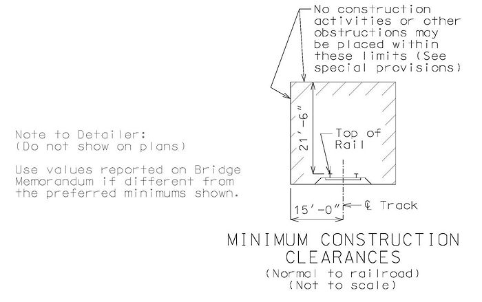
For existing and new railroads in operation during construction, the following railroad minimum construction clearance detail shall be provided near the General Elevation Detail.
751.5.2.1.2.8 Slope Protection
When rock blanket is specified on the Bridge Memorandum or Design Layout, it is to be shown in the General Elevation Detail, typically in combination with the slope criteria. The following figure shows common rock blanket details. See EPG 751.1.2.15 Bridges over Railroad for criteria specific to bridges over railroads.
Note:
- When permanent erosion control geotextile is specified on the Bridge Memorandum or Design Layout, it shall be specified with the rock blanket. Permanent erosion control geotextile material shall be used under slab drains in combination with rock blanket.
- The 100-year flood elevation and flow depth (D) are shown for illustration and are not to be shown on the plans.
- (a) Rock blanket on the spill fill slopes shall be shown to the elevation specified on the Bridge Memorandum or Design Layout in accordance with EPG 751.1.2.29 Protection of Spill Slopes and Side Slopes. If the Bridge Memorandum or Design Layout specifies extending the rock blanket above this elevation to provide slope protection beneath slab drains (as shown on the right side of above drawing), the top of the rock blanket on the side slope may be shown with elevation specified. Otherwise the elevation and detail need not be shown.
- (b) A rock blanket apron should extend from the toe of the spill slope into the bridge waterway a distance equal to twice the 100-year flood flow depth D in the overbank area near the embankment, but need not exceed 25 feet.
- (c) See the Bridge Memorandum or Design Layout for specified slope of spill fill. Maximum allowable spill fill slope is determined by Construction and Materials Division as specified in the soils survey for each project.
751.5.2.1.2.9 Miscellaneous Notes for the General Elevation Detail
Applicable notes of EPG 751.50 E1. Excavation and Fill and E3. Miscellaneous, shall be placed near the General Elevation Detail.
751.5.2.1.2.10 Miscellaneous Details for the General Elevation Detail
- If fencing is located on the structure, only a small portion of the fencing need be shown at each end of the structure and labeled at one of the locations as “Pedestrian Fence” for chain link fences and “Decorative Fence” for all other types of fences.
- Outline of remaining portions of existing substructure components that are in close proximity to new substructure.
- Temporary shoring required for construction and specified as a roadway item, if applicable.
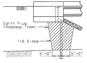
- When earth plugs are required due to Class C roadway fill, the earth plug and bottom width and slope of plug shall be specified as shown. The Class C roadway fill need not be shown or specified.
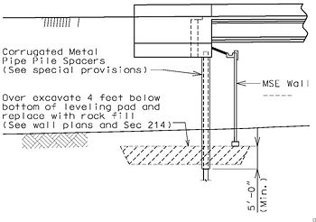
- MSE walls shall be shown, including coping, leveling pad, pile spacers and, if required, gutter and over excavation of unsuitable foundation material. The wall number, spacers, depth of spacers below leveling pad and over excavation shall be specified as shown.
- Outline of new or existing underground utilities that may cause construction difficulties due to the close proximity to new substructure.
- Signs or lighting attached to the structure shall be shown and labeled if space allows, but may be omitted if required for clarity.
- The location of overhead power lines that may cause construction difficulties shall be shown using an oval or circle Bridge-Miscellaneous object line labeled “Overhead Power Lines”.
751.5.2.1.3 Information Blocks
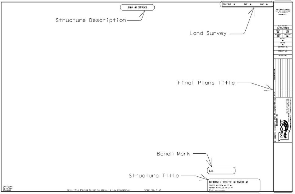
EPG 751.5.2.1.3 Information Blocks provides instructions for filling out required information blocks. The following picture shows each of the required information blocks, and the sections that follow provide instruction for filling out each block.
751.5.2.1.3.1 Structure Description
A description of each of the superstructure types shall be provided at the top of the front sheet.
For bridges, this description consists of the span configuration and the type of superstructure followed by “SPAN” or “SPANS” as required.
The following elements are used to define the span configuration:
- Parentheses indicate a break in continuity
- Dashes and commas indicate level of continuity, see examples
- Span lengths that are partial foot lengths shall be reported to the nearest tenth foot.
| Examples of Bridge Span Configurations | |
|---|---|
| Configuration | Explanation |
| (98’) | Single span |
| (35’)(40’)(35’) | Multiple simple spans with deck joints at each intermediate bent |
| 5@(40’) | Multiple simple spans of the same length with deck joints at each intermediate bent |
| (35’)5@(40’)(35’) | Multiple simple spans including a series of same length spans and with deck joints at each intermediate bent |
| (35’,40’,35’) | Multiple simple spans with a continuous deck |
| (5@45’) | Multiple simple spans of the same length with a continuous deck (type of superstructure would need to start with “SIMPLE”) |
| (35’,5@40’,35’) | Multiple simple spans with a continuous deck including a series of same length spans |
| (65’-85’-65.4’) | Unit of continuous spans |
| (5@45’) | Unit of continuous spans of the same length |
| (65’-3@85’-65’) | Unit of continuous spans including a series of same length spans |
| (100’-120’-110’)(120’-180’-120’) | Two units of continuous spans separated by a deck joint |
| 2@(120’-180’-120’) | Two identical units continuous spans separated by a deck joint |
| (65’)(120’-180’)(65’) | Simple spans in combination with a unit of continuous spans separated by a deck joint |
| Short hand notation if used defaults to the continuous configuration if it cannot be interpreted otherwise. For example (5@45’) means continuous spans however (40’,5@45’,45) means a continuous deck over simple spans. Short hand notation should not be used with decks that are continuous over both simple and continuous spans. | |
| Common Types of Bridge Superstructures | ||
|---|---|---|
| Precast Concrete | Steel1 | Cast-In-Place Concrete |
| PRESTRESSED CONCRETE I-GIRDER |
COMPOSITE WIDE FLANGE BEAM | CONTINUOUS CONCRETE SOLID SLAB3 |
| PRESTRESSED CONCRETE BULB-TEE GIRDER |
COMPOSITE PLATE GIRDER | CONTINUOUS CONCRETE VOIDED SLAB3 |
| PRESTRESSED CONCRETE NU-GIRDER |
WIDE FLANGE BEAM2 | CONTINUOUS CONCRETE BOX GIRDER3 |
| PRESTRESSED CONCRETE SPREAD BOX BEAM |
PLATE GIRDER2 | CONCRETE DECK GIRDER |
| PRESTRESSED CONCRETE ADJACENT BOX BEAM |
||
| PRESTRESSED CONCRETE SPREAD VOIDED SLAB BEAM | ||
| PRESTRESSED CONCRETE ADJACENT VOIDED SLAB BEAM | ||
| PRESTRESSED CONCRETE SOLID SLAB BEAM | ||
| PRESTRESSED CONCRETE DOUBLE-TEE GIRDER | ||
| 1 “CONTINUOUS” or “SIMPLE” shall be specified as required for multiple span structures. | ||
| 2 Non-composite is not required to be specified for steel structures. | ||
| 3 “CONTINUOUS” not required for single span structures. | ||
For culverts, the structure description consists of the cell configuration and the type of culvert. The description ends with CULVERT and is followed with ON ROCK for box culverts without a bottom slab.
| Examples |
|---|
| 3(8’x8’) CONCRETE BOX CULVERT |
| 2(8’x9.5’) CONCRETE BOX CULVERT ON ROCK |
| 5(6’) CORRUGATED STEEL PIPE CULVERT |
For existing structures that are being modified and/or rehabilitated, the structure description shall start with “U.I.P.” followed by a list of all superstructure work followed by “EXISTING” followed by the span configuration and type of structure. Rehabilitate covers a range of work, including but not limited to slab repair, adding or replacing wearing surfaces, adding curb blockouts and replacing slab overhangs. When removing joints from an existing superstructure or relocating the joints to the intermediate bents, add “TO” after “EXISTING”.
| Types of Typical Work and the Order Listed if the Work is Applicable |
Redeck, Widen, Seismic Retrofit, Strengthen, Make Composite, Extend (culverts), Rehabilitate and Reconfigure |
| Various Examples (span/cell configuration and type of structure not shown) |
U.I.P. AND REHABILITATE EXISTING… U.I.P., REDECK AND REHABILITATE EXISTING… U.I.P., REDECK AND MAKE COMPOSITE EXISTING… U.I.P., STRENGTHEN AND REHABILITATE EXISTING… U.I.P., WIDEN AND REHABILITATE EXISTING… U.I.P. AND EXTEND EXISTING… U.I.P., EXTEND AND REHABILITATE EXISTING… U.I.P., REDECK AND RECONFIGURE EXISTING TO… |
Replacing the entire superstructure is an exception to the above rules. For superstructure replacements, a list of all substructure work shall specified followed by “EXISTING SUBSTRUCTUE AND REPLACE SUPERSTRUCTURE WITH” followed by the new span configuration and type of structure.
| Examples (span configuration and type of structure not shown) |
| U.I.P. EXISTING SUBSTRUCTURE AND REPLACE SUPERSTRUCTURE WITH… |
| U.I.P. AND REHABILITATE EXISTING SUBSTRUCTURE AND REPLACE SUPERSTRUCTURE WITH… |
| U.I.P., WIDEN AND REHABILITATE EXISTING SUBSTRUCTURE AND REPLACE SUPERSTRUCTURE WITH… |
751.5.2.1.3.2 Land Survey
The section or survey (SEC/SUR), township (TWP) and range (RGE) of the Public Land Survey System where the structure is located shall be indicated using small bold text in the land survey block in the upper right corner of the sheet.
751.5.2.1.3.3 Final Plans Title
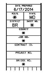
The final plans title block shall be provided on all sheets. The following job-specific information needs to be filled in: project route, sheet number, county, job number and bridge number. Date Prepared fills in automatically when the sheet is printed. Consultant-prepared plans shall also include the consultant’s logo, address and license number in the area provided directly below the Commission’s title.
751.5.2.1.3.4 Bench Mark
The elevation and location of a bench mark in the vicinity of the structure shall be provided just above the structure title block using small bold text. This information shall be typed exactly as shown on the plat sheet of the bridge survey (typically all uppercase but not always).
751.5.2.1.3.5 Structure Title
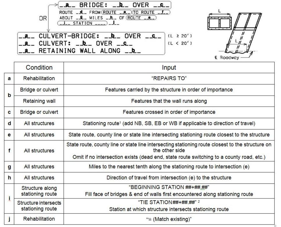
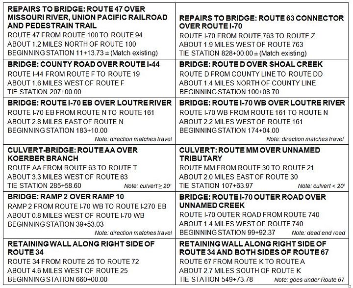
Features spanned, structure location along the stationing route, and the reference station shall be included in the structure title block, located directly to the left of the standard plans block.
- Note:
- Do not use “MO” or “US” in front of state route numbers or letters.
- Use specific names for rivers, streams, state routes, railroads, city streets and county roads. Specific names not required for private roads, pedestrian trails, state and county lines.
- 1 The stationing route is always the project route for bridges and culverts that carry or intersect the project route and for walls parallel the project route. For bridges, culverts and walls that do not directly involve the project route such as outer roads or secondary state routes, the stationing route is the state route carrying, intersecting or parallel to the structure.
- The project route is the route the entire project is associated with and is always listed in the final plans title block on the right hand side of the sheet.
- 2 Should not be confused with a “tie station” on a Bridge Memo used to locate a specific bent with respect to route for purposes of design only. For example, stream piers are sometimes “tied” so a designer knows not to locate it differently. However, plans need not show this station.
- Note:
Examples of Structure Title Block
751.5.2.1.4 Section Thru Existing Deck Detail
For rehabilitation of existing bridges a Typical Section Thru Deck Detail is shown instead of the Plan and General Elevation Details. All deck repairs should be specified in this detail.
| Detailing Guidance |
|---|
| EPG 751.40 Widening and Repair (Non-LRFD) |
| Bridge Standard Drawings |
| Deck Rehabilitation |
| Deck Replacement |
751.5.2.1.5 Supplementary Details
This subarticle provides guidance on several supplementary details that may be required, dependent on the type of structure. These details, if required, shall be placed on the front sheet if space allows. Otherwise, they shall be placed on the General Notes and Estimated Quantities Sheet.
751.5.2.1.5.1 Location Sketch
A Location Sketch shall be provided for all structures, including culverts and retaining walls. The Location Sketch may be eliminated on grade separation structures, except where payment is made for removal of an existing structure, or a congested area is involved such as a series of ramps, extended slope protection, etc. When a Location Sketch is provided for a grade separation, the tie station of both alignments shall be shown.
The Location Sketch for stream crossings shall show the outline of the stream channel at the bridge site. The name of the stream shall be given and the direction of flow indicated by an arrow labeled "Flow". Any required channel change shall be shown and labeled "Proposed Channel Change (See roadway plans)”.
The centerline of the roadway shall be shown and noted. The beginning station and outline of the new bridge shall be shown, and the new bridge labeled "Proposed Structure". The existing bridge, if any, shall be shown and labeled "Existing Structure". If it is a state bridge that is to be removed, the bridge number shall be indicated. Place the north arrow near the Location Sketch.
When the Location Sketch is placed on the front sheet, all horizontal curve data of roadways going over, under, or within 150 feet of the structure shall be provided nearby.
751.5.2.1.5.2 Foundation Data
See EPG 751.50 E2. Foundation Data Table for appropriate data to be included in the foundation data table and notes required below the table.
751.5.2.1.5.3 Hydraulic Data
751.5.2.1.5.3.1 Data Tables
The following tables for hydrologic data are required on all bridge and box culvert stream crossings. The hydrologic data shall be provided on the Bridge Memorandum or the Design Layout. The appropriate table shall be placed near the Location Sketch.
- (1) See EPG 748.2 Roadway Design Critera
- (4) See EPG 748.3.5 Bridges and Culverts. Flooding source for freeboard should be recorded in the table when minimum freeboard is not from headwater flow.
- (5) See EPG 750.3.2.4.5 Overtopping Discharge and Frequency
- Provide discharge if frequency equals 500 years or less, otherwise record as “N/A”.
- (6) See EPG 750.3.2.4.5 Overtopping Discharge and Frequency
- Provide frequency if frequency equals 500 years or less, otherwise record as “> 500 years”.
- (7) Insert “Overtopping” and provide the Overtopping Flood (EPG 749.2.3) elevation if frequency equals 500 years or less, otherwise insert “500-Year” and provide the 500-year flood elevation.
- *' Omit rows in table if the Design Flood Frequency is for a 100-year flood event
751.5.2.1.5.3.2 Accuracy
Formulas upon which hydraulic calculations are based are approximations which have been developed from model studies, stream gaging and/or statistical analysis. The hydraulic design formulas therefore are considered to be approximations. Due to the diverse nature of individual drainage basins, considerable engineering judgment must be exercised in hydraulic design to obtain reasonable and practical results. Due to these factors, accuracy used in hydrologic calculations and reported in the hydrologic data tables is to the accuracy listed below.
| Accuracy of Hydrologic Data | ||
|---|---|---|
| Hydrologic Data | Data Limit | Accuracy |
| Drainage Area | Less than 10 mi2 | 0.1 mi2 |
| Greater than 10 mi2 | 1.0 mi2 | |
| Estimated Discharge | Less than 2000 cfs | 10 cfs |
| Greater than 2000 cfs | 100 cfs | |
| Velocities | All | 0.1 ft/s |
| Water Surface Elevations | All | 0.1 ft |
751.5.2.2 General Notes and Estimated Quantities
Typically, the second sheet of bridge plans for new structures and the widening or extension of existing structures shows the general notes and estimated quantities applicable to the entire structure. For culverts, retaining walls and rehabilitation of existing bridges there is typically enough room on the front sheet for these items. This section provides detailing guidance for these items.
751.5.2.2.1 General Notes
Applicable notes from EPG 751.50 A. General Notes, shall be placed on this sheet in the order given, based on structure type and information provided in the Bridge Memorandum or Design Layout and design computations. The General Notes typically are shown on the same sheet as the Estimated Quantities.
751.5.2.2.2 Estimated Quantities
Applicable quantity tables and the corresponding notes from EPG 751.50 B. Estimated Quantities Notes shall be placed on this sheet. Typically, the Estimated Quantities Table for the entire structure is placed on the same sheet as the General Notes, with supplementary quantity tables placed below, where space allows. The quantity tables shall be filled out based on the structure’s estimated quantities computations, in accordance with EPG 751.6 General Quantities.
751.5.2.3 Staged Construction
When the structure is to be built in stages to allow traffic during construction, the details shall be placed on the Staged Construction Sheet, in accordance with requirements specified in the Bridge Memorandum or Design Layout. In a set of bridge plans, this sheet, when required, shall follow the General Notes and Estimated Quantities Sheet.
751.5.2.4 Substructure Layout (Curved Bridges)
For horizontally curved bridges, a substructure layout more detailed than that provided on the Plan and General Elevation sheet shall be added after the Staged Construction sheet, if applicable; otherwise it shall be placed after the General Notes and Estimated Quantities sheet. The following sketches show the form and content to be used in detailing the substructure layout for some of the most common horizontal curve situations. When situations arise where modification of these sketches becomes necessary, the sketches should be used as a guide with regard to the form and content of the modified layout.
| Substructure Layout Sheet Table of Contents |
|---|
| 1. Bents Located Using Span Chords |
| 2. Bents Located Using Long Chord (Tangent girders and curved deck with varying overhangs) |
| 3. Built Tangent along Long Chord (Deck slightly wider with roadway striped on a curved) |
751.5.2.4.1 Bents Located Using Span Chords
Attention should be given to the fact that in all cases illustrated here, the centerline of the roadway passes through the geometric center of the intermediate bents. On occasion, particularly in the case of continuous prestressed concrete bridges, or with unsymmetrical roadways, this will not happen. In these and any other case which may cause a similar situation, Dimension D, from the intersection of the centerline of the roadway and the longitudinal centerline of the bent, to the geometric center of the bent, must be shown. The orientation of the bents shall be as noted in the Bridge Memorandum or Design Layout. Typically, all bents of concrete bridges will be parallel to a line at a particular station, while bents of steel structures will be aligned radially or have the same skew.
The following key describes the dimensions marked on the following four figures:
| (1) Dimension along tangent | (7) Angle between fill face and chord |
| (2) Offset from the tangent | (8) Angle between fill face and radial line |
| (3) Angle between chords of adjacent spans | (9) Angle between tangent and chord |
| (4) Chord length | (10) Skew angle |
| (5) Dimension along centerline median or roadway | (11) Dimension from centerline median to centerline lane along centerline
bent |
| (6) Angle between centerline bent and chord | (12) Dimension from centerline median to centerline lane along fill face |
751.5.2.4.1.1 Dual Lane Structures Tied at Fill Face of End Bent
751.5.2.4.1.2 Single Lane Structure Tied at Fill Face of End Bent
751.5.2.4.1.3 Dual Lane Structure Tied at Intersection
751.5.2.4.1.4 Single Lane Structure Tied at Intersection
751.5.2.4.2 Bents Located Using Long Chord (Tangent girders and curved deck with varying overhangs)
When noted on the Bridge Memorandum or Design Layout, short bridges on small horizontal curve alignments may be detailed on a line parallel to the long chord. The intent is to simplify the bridge geometry by placing the centerline of steel or P/S assembly on or parallel to the long chord to the centerline of roadway curve between fill faces of end bents. In order to avoid excessive slab overhangs, the line parallel to the long chord is usually placed at one-half the mid ordinate between curve and long chord. For this situation, the outside faces of the slab, barrier or railing, and wings shall be detailed concentrically with the roadway curvature, and curve ordinates shall be furnished on the plans.
It is to be noted that even for symmetrical width bridges, the location of bearings will not be symmetrical about the centerline of bents. Also, the intermediate bent caps shall be built to sufficient length on each end to accommodate the bearing offsets toward each end.
751.5.2.4.2.1 Squared and Symmetrical Roadway and Spans
751.5.2.4.2.2 Squared and Unsymmetrical Roadway, Symmetrical Spans
751.5.2.4.2.3 Skewed and Symmetrical Roadway and Spans
751.5.2.4.3 Built Tangent along Long Chord (Deck slightly wider with roadway striped on a curve)
For wide roadways and very small degrees of curvature for which the mid ordinates are 3 inches or less, the Bridge Memorandum or Design Layout may occasionally direct that the entire bridge be detailed as a tangent bridge along the long chord. For this situation, no parts of the bridge are to be curved. Details for the plan view on the plan and general elevation sheet shall be in accordance with EPG 751.5.2.1.1.1 Plan View, except that the centerline of structure will be on the long chord. A supplementary bridge substructure layout sheet shall not be required for this type of layout.
751.5.3 Bridge Substructure Sheets
751.5.3.1 End Bents
| Bridge Standard Drawings |
| Cast-In-Place Pile |
| Deadman Anchor Systems |
751.5.3.2 Vertical Drain at End Bents
| Bridge Standard Drawings |
| Vertical Drain at End Bents |
751.5.3.3 Intermediate Bents
| Bridge Standard Drawings |
| Cast-In-Place Pile |
| As Built Drilled Shaft Data |
751.5.3.4 Bearings
| Detailing Guidance |
|---|
| EPG 751.11 Bearings |
| EPG 751.40 Widening and Repair (Non-LRFD) |
| Bridge Standard Drawings |
| Bearings |
751.5.4 Bridge Superstructure Sheets
751.5.4.1 Precast P/S Concrete Girders and Beams
| Detailing Guidance |
|---|
| EPG 751.22 P/S Concrete I Girders |
| EPG 751.23 P/S Concrete Double Tee |
| EPG 751.40 Widening and Repair (Non-LRFD) |
| Bridge Standard Drawings |
| Prestressed Concrete I-Girders |
| Prestressed Concrete Box Beams |
| Steel Intermediate Diaphragms |
751.5.4.2 C.I.P. Girders and Slabs
| Detailing Guidance |
|---|
| EPG 751.17 Concrete Slab Bridges |
| EPG 751.18 Concrete Multicell Box Girder Bridges |
| EPG 751.40 Widening and Repair (Non-LRFD) |
751.5.4.3 Steel Plate Girders and Wide Flanges Beams
| Detailing Guidance |
|---|
| EPG 751.14 Steel Superstructure |
| EPG 751.40 Widening and Repair (Non-LRFD) |
751.5.4.4 Expansion Devices
| Detailing Guidance |
|---|
| EPG 751.13 Expansion Devices |
| EPG 751.40 Widening and Repair (Non-LRFD) |
| Bridge Standard Drawings |
| Expansion Devices |
| Joint Seals |
751.5.4.5 Bridge Decks
| Detailing Guidance |
|---|
| EPG 751.10 General Superstructure |
| EPG 751.40 Widening and Repair (Non-LRFD) |
| Bridge Standard Drawings |
| Slab Sections |
| Precast Prestressed Deck Panels |
| Slab Drains |
| Deck Rehabilitation |
| Deck Replacement |
751.5.4.6 Barrier and Railing
| Detailing Guidance |
|---|
| EPG 751.12 Barriers, Railings, Curbs and Fences |
| EPG 751.40 Widening and Repair (Non-LRFD) |
| Bridge Standard Drawings |
| Concrete Barrier |
| Thrie Beam Railing |
| Two Tube Railing |
| Curb Blockout and Barrier End Modification |
| Guardrail Attachment to Box Culverts |
751.5.5 Culvert Sheets
| Detailing Guidance |
|---|
| EPG 751.8 Concrete Box Culverts |
| Bridge Standard Drawings |
| Box Culverts - BXC |
751.5.6 Retaining Wall Sheets
| Detailing Guidance |
|---|
| EPG 751.24 Retaining Walls |
| Bridge Standard Drawings |
| MSE Wall - MSEW |
751.5.7 Temporary Bridge Sheets
| Bridge Standard Drawings |
| Temporary Bridge |
751.5.8 Miscellaneous Sheets
751.5.8.1 Bridge Approach Slab
Place the bridge approach slab sheet(s) before the bill of reinforcing steel sheet(s).
| Detailing Guidance |
|---|
| EPG 751.10.5.1 Timber Header |
| Bridge Standard Drawings |
| Bridge Approach Slabs |
751.5.8.2 Bill of Reinforcing Steel
| Bridge Standard Drawings |
| Bill of Reinforcing Steel |
751.5.8.3 As-Built Pile and Drilled Shaft Data
Place the as-built pile and drilled shaft data sheet(s) after the bill of reinforcing steel sheet(s).
| Bridge Standard Drawings |
| As Built Pile Data |
| As Built Drilled Shaft Data |
751.5.8.4 Boring Data
Place the subsurface profile(s) at the end of the plans set. All subsurface profiles shall be reprinted without modifying any information.
The boring location note provided in EPG 751.50 E3 Miscellaneous shall be placed below the sheet title (Note E3.4). This note is already included on the Boring Data Standard Drawing.
| Bridge Standard Drawings |
| Borings - BOR / Boring Template |
751.5.8.5 Pedestrian Railing
| Detailing Guidance |
|---|
| EPG 751.12.4 Chain Link Fence |
| Bridge Standard Drawings |
| (Fences-FEN) |
751.5.8.6 Conduit
| Detailing Guidance |
|---|
| EPG 751.10.4 Conduit Systems |
751.5.9 Miscellaneous Details
751.5.9.1 Joint Filler
When joint filler is indicated on any sheet of the plans, the required type of joint filler shall be specified in either the detail or a note.
| Types of Joint Filler, Sec 1057 | Typical Application |
|---|---|
| Preformed Sponge Rubber Expansion and Partition Joint Filler | Superstructure (except P/S panels), Pedestrian Structures and Retaining Walls |
| Preformed Fiber Expansion Joint Material | Bridge Approach Slabs, Culverts, Slope Protection and P/S Panels |
For bridges and retaining walls, preformed sponge rubber expansion and partition joint filler shall be specified in the General Notes, and therefore only details utilizing preformed fiber expansion joint material require identifying this type of joint filler.
751.5.9.2 Reinforcing Steel
| Reinforcing Steel Table of Contents | ||
|---|---|---|
| 1. General | 2. Epoxy Coated | 3. Available Sizes |
| 4. Length Limits | 5. Spacing Limits | 6. Cover Limits |
| 7. Length Calculations | 8. Development and Lap Splices | 9. Mechanical Bar Splices |
751.5.9.2.1 Reinforcing Steel General
Unless otherwise specified, reinforcement shall be Grade 60 deformed bars, meeting the requirements of AASHTO M31, except that plain bars, deformed wire or plain wire may be used for spirals. Welded wire reinforcement shall be deformed when used as a substitute for deformed bars. Details for dimensioning reinforcing steel shall be in accordance with the Concrete Reinforcing Steel Institute Manual of Standard Practice.
751.5.9.2.1.1 Reinforcing Callouts
Dimensions and Leader Notes
All reinforcing steel that is included in a bill of reinforcing steel shall be specified in dimensions and leader notes using reinforcing callouts specifying both quantity and bar mark.
One of the two following formats shall be used for callouts:
| Bars Placed Individually | Bars Placed as Pairs | |
| A-#B-CD | A Pr.-#B-CD |
- Where:
- A = quantity
- B = bar size
- C = descriptive letter
- D = number
Omit quantity if only one bar or pair of bars is being specified. The abbreviation for pair(s) shall always be used for callouts.
The bar mark (#B-CD) consists of the bar size hyphenated with a bar designation (#6-H100).
Notes
Callouts are not used in notes. Instead, the quantity of bars (including if placed as pairs) shall be specified with the bar mark in accordance with EPG 751.5.1.1.10 and EPG 751.5.1.3. (Two pairs of #4-U100 bars …)
Bar Designation
Bar designation consists of a descriptive letter followed by a number typically unique to a desired shape or length. The following descriptive letter shall be used for the following locations.
- A – Top & bottom slabs of box culverts
- B – Walls of box culverts
- C – Slip-forming bars in barriers
- D – Culvert headwalls; dowel bars in intermediate bent keys; footings
- E – Vertical bars at end of culvert wing walls
- F – Culvert walls and slabs; corner and wing brace bars in end bents
- G – Culvert wing walls
- H – Horizontal bars in end bents, intermediate bents, concrete diaphragms, culvert slabs
- J – L-shaped bars and top of wings in culverts
- K – Type B, D & H barriers at end bents
- M – Type C Barrier (except for required slip-forming bars)
- P – Stirrup in columns, drilled shafts, & CIP piles
- R – Type A, B, D & H Barriers (except for slip-forming bars & bars at end bents); culvert head walls
- S – Slab
- U – Stirrup bars in end bents, intermediate bents, and concrete diaphragms
- V – Vertical bars in columns, drilled shafts, CIP piles, end bent beams, concrete diaphragm
- W – Wire in a spiral for anchor bolt holes (and size starts with a W instead of “#”, e.g. “W5-W100”)
It is recommended to use 3 digits for the number designation (H100 instead of H10, for example) to allow for plenty of numbers for structures with a lot of different bars. Normally a 100 series would be used for End Bent No. 1 (or Unit 1 on a culvert), 200 series for Bent 2, etc. Exceptions are S bars in the slab, and C, K and R bars in barriers, which use one digit (S1, S2, S3, etc.).
751.5.9.2.1.2 Bend Shapes
Types:
There are two types of bend shapes: standard pin bend shapes and stirrup pin bend shapes.
Standard pin bend shapes are bent around standard pins and have a finished bend diameter in accordance with that specified on the bridge plans. Standard 90° and 180° hooks (used in development of bars) are bent around standard pins in accordance with the hook dimensions specified on the bridge plans.
Stirrup pin bend shapes are bent around stirrup pins and have a finished bend diameter in accordance with that specified on the bridge plans. Stirrup 90°, 135° and 180° hooks are bent around stirrup pins in accordance with the hook dimensions specified on the bridge plans. The stirrup 180° hooks of Shape 37S may be used instead of the standard 180° hooks when lapping the stirrup bars for shallow structures.
Shape Number:
There are 33 standard bend shapes shown with the Bill of Reinforcing Steel on every set of bridge plans. These bend shapes are specified by the numbers 6 thru 38. The letter “S” indicates the shape is a stirrup pin bend shape, otherwise the shape is a standard pin bend shape. Many of the legs of the standard shapes may be omitted as needed to create the required shape.
Seventeen of the standard shapes may be specified as either a standard pin bend shape or a stirrup pin bend shape (6, 8, 9,10, 11, 14, 15, 19, 21, 23, 24, 25, 28, 29, 30, 32 & 33). Ten of the standard shapes may only be specified as a standard pin bend shape (7, 12, 16, 17, 18, 20, 22, 26, 35 & 36). Six of the standard shapes may only be specified as a stirrup pin bend shape (13, 27, 31, 34, 37 & 38).
Non-standard shapes may be used when an unusual shape is required, and the shape can’t be obtained from one of the standard shapes. The bending diagram of non-standard shapes are added to the bill of reinforcing steel when required, starting with shape number 50.
Fabrication:
Shapes are fabricated in accordance with the latest version of the CRSI Manual of Standard Practice, except fabricators shall use the finished bend diameters and hook dimensions specified on bridge plans. MoDOT deviates from CRSI as follows:
- Use ACI’s finished bend diameter for #4 and #5 stirrup pin bend shapes (4d instead of CRSI’s 5d).
- Dimension A or G is rounded up to next quarter-inch increment. (CRSI rounds to nearest inch increment for standard pin bend shapes and to nearest quarter-inch increment for stirrup pin bend shapes. CRSI’s rounding does not always provide the bar length needed for minimum extension of the hook).
- Dimensions H and J are rounded to the nearest eighth-inch increment (instead of nearest quarter-inch increment).
- Bar sizes 7 and 8 are not used in stirrup pin bend shapes.
751.5.9.2.2 Epoxy Coated Reinforcement Requirements
Reinforcement shall be uncoated bar unless otherwise noted.
Bridge Superstructure. All reinforcement in integral end bents shall be epoxy coated including CIP pile reinforcement but excluding drilled shaft reinforcement. All reinforcement in diaphragms, slab and barrier or railing shall be epoxy coated.
Non-Integral End Bents. All reinforcement shall be epoxy coated including CIP pile reinforcement but excluding drilled shaft reinforcement.
Intermediate Bents. When below an expansion device or when subject to spraying from adjacent roadways (15 feet or less from edge of shoulder), all reinforcement that is partially or entirely above ground shall be epoxy coated including CIP pile reinforcement but excluding drilled shaft reinforcement with greater than 3 inches of concrete cover. Coating of dowel bars shall be same as coating of intermediate bent reinforcement.
MSE Retaining Walls. When subject to spraying from adjacent roadways (15 feet or less from edge of shoulder), all panel and coping reinforcement shall be epoxy coated. The potential for future widening shall be considered. Epoxy coated reinforcement shall also be considered (regardless of location) where panels will be continuously wetted (around sources of water) and for structurally critical applications, such as containing necessary fill around structures.
Cast-In-Place Retaining Walls. When subject to spraying from adjacent roadways (15 feet or less from edge of shoulder), all reinforcement that is partially or entirely above ground shall be epoxy coated including CIP pile reinforcement but excluding drilled shaft reinforcement. The potential for future widening of adjacent roadway shall be considered.
Box Culverts. Epoxy coated reinforcement should be considered for fills 1 foot or less. Culverts located underneath heavily travelled roadways or sagging vertical curves are good candidates for use of epoxy. See the Structural Project Manager or Structural Liaison Engineer to determine the level of epoxy implementation (i.e. top slab only).
751.5.9.2.3 Available Sizes
751.5.9.2.3.1 Bar Sizes
For general use, reinforcement may range from #4 through #11 bars with restrictions as described for individual structural components. Number 14 and #18 bars shall not be used without the permission of the Structural Project Manager or Structural Liaison Engineer. Number 14 and #18 bars may be used in drilled shafts and rock sockets if #11 or small bars will not work.
751.5.9.2.3.2 Bar Support Heights
The height of all reinforcing bar supports shall be carried to the nearest 1/4". See Missouri Standard Plans Drawing 706.35 for details of bar supports.
751.5.9.2.4 Length Limits
Minimum length: Minimum reinforcement length shall be 2'-0", except for dowel bars and anchor bars.
Maximum length: Maximum reinforcement length shall be as follows:
| Uncoated Reinforcement | |
|---|---|
| #4 bars and larger | 60'-0" |
| Epoxy Coated Reinforcement | |
| #4 bars and larger | 60'-0" |
751.5.9.2.5 Spacing Limits
Reinforcement spacing shall be in accordance with LRFD 5.10.3, unless modified by the following criteria or elsewhere shown in the EPG.
| Minimum Spacing - Moment Reinforcement | |
|---|---|
| Preferred Min. - Footings | 6" centers |
| Preferred Min. - Slabs, Culvert Walls and Retaining Walls | 6" centers |
| Absolute Min. - Slabs, Culvert Walls and Retaining Walls | 5” centers |
| Preferred Min. - All Other | 4” centers |
| Absolute Min. | 2 1/2” clear |
| Maximum Spacing - Moment Reinforcement | |
| Absolute Max. - Slabs | 1.5(slab thickness) |
| Absolute Max. - All Other | 18" |
| Minimum Spacing - Shear Reinforcement | |
| Absolute Min. - Substructure Beams (single stirrups) | 5" centers |
| Absolute Min. - Substructure Beams (double Stirrups) | 6" centers |
| Absolute Min. - Prestressed Slab Beams, Box Beams and I Girders | 5" centers |
| Maximum Spacing - Shear Reinforcement | |
| Absolute Max. - Substructure Beams | 12" centers |
| Absolute Max. - Prestressed Slab Beams, Box Beams and I Girders | Refer to EPG 751.22 P/S Concrete I Girders |
| Minimum Spacing - Longitudinal Compression Reinforcement | |
| Absolute Min. | 4 1/2" centers |
| Absolute Min. - Cols. (thru #10) | 2" clear |
| Absolute Min. - Cols. (#11, #14) | 2 1/2" clear |
| Absolute Min. - Cols (#18) | 3 1/2” clear |
| For Drilled Shafts and Rock Sockets, see EPG 751.37.6.1 Reinforcement Design. | |
| Minimum Pitch - Spiral Reinforcement for Compression Members (Static) | |
| For Columns, Drilled Shafts, Rock Sockets | See LRFD |
| Minimum Spacing- Ties (Transverse) Reinforcement for Compression Members (Static) | |
| For Columns | See LRFD |
| For Drilled Shafts and Rock Sockets, see EPG 751.37.6.1 Reinforcement Design. | 6” centers for #4 bars |
| Maximum Spacing - Longitudinal Compression Reinforcement | |
| Absolute Max. - the minimum number of longitudinal reinforcing bars shall be six for circular members and four for bars in a rectangular arrangement. For other requirements, see LRFD | |
| Maximum Pitch - Spiral Reinforcement for Compression Members (Static) | |
| Absolute Max. - Spirals | 6” pitch |
| Maximum Spacing - Ties (Transverse) Reinforcement for Compression Members (Static) | |
| Absolute Max. - Ties | 12" centers |
| Minimum & Maximum Pitch- Spiral Reinforcement for Compression Members (Seismic) | |
| See EPG 751.9 Bridge Seismic Design | |
751.5.9.2.6 Cover Limits
| Situation | Minimum Cover | |
|---|---|---|
| Concrete cast against and permanently exposed to earth: | ||
| - primary reinforcement | 3" | |
| - stirrups, ties, spirals | 2 1/2" | |
| Conc. exposed to earth or weather: | ||
| - primary reinforcement | 2" | |
| - stirrups, ties, spirals | 1 1/2" | |
| Conc. slabs which have no positive corrosion protection: | ||
| - top reinforcement | 3" * | |
| - bottom reinforcement | 1" | |
| Conc. not exposed to weather or in contact with ground: | ||
| - primary reinforcement (thru #11) | 1 1/2" | |
| - stirrups, ties, spirals | 1" | |
| Conc. piles cast against or permanently exposed to earth | 2" | |
| * Absolute minimum cover shall be 2½ inches by LRFD 5.12.3. The minimum cover for stirrup and tie steel shall be 1½ inches unless otherwise specified. For minimum cover for drilled shafts and rock sockets, see EPG 751.37.6.1 Reinforcement Design. | ||
751.5.9.2.7 Length Calculations
Lengths of individual legs of shaped reinforcing bars shall be out to out dimensions using ¼-inch increments and rounded as required to maintain clearances. Lengths of straight reinforcing bars shall be determined using one-inch increments and rounded down to maintain clearances or rounded up to achieve proper lap.
Nominal lengths, listed for fabricators use, is the summation of the individual out to out lengths. Actual lengths, listed for determining weight, is the length along the centerline of bar. Nominal and actual lengths shall be rounded to the nearest inch.
751.5.9.2.7.1 Standard Pin Bend Shapes (All Grades)
Hook Dimensions A or G and J:
Dimension A or G is rounded up to the next quarter-inch increment to insure adequate extension of hook.
Dimension J is rounded to the nearest eighth-inch increment.
| Bar Size | d | D | r | R | 90° Hooks | 180° Hooks | ||
| A or G | C | A or G | J | |||||
| #4 | 0.500" | 3.00" | 1.750" | 2.000" | 8" | 5.498" | 6" | 4" |
| #5 | 0.625" | 3.75" | 2.188" | 2.500" | 10" | 6.872" | 7" | 5" |
| #6 | 0.750" | 4.50" | 2.625" | 3.000" | 12" | 8.247" | 8¼" | 6" |
| #7 | 0.875" | 5.25" | 3.063" | 3.500" | 14" | 9.621" | 9¾" | 7" |
| #7ga | 0.875" | 7.00" | 3.938" | 4.375" | 15" | 12.370" | 11½" | 8¾" |
| #8 | 1.000" | 6.00" | 3.500" | 4.000" | 16" | 10.996" | 11" | 8" |
| #8ga | 1.000" | 8.00" | 4.500" | 5.000" | 17" | 14.137" | 13¼" | 10" |
| #9 | 1.128" | 9.50" | 5.314" | 5.878" | 19½" | 16.694" | 15½" | 11¾" |
| #10 | 1.270" | 10.75" | 6.010" | 6.645" | 22" | 18.881" | 17½" | 13¼" |
| #11 | 1.410" | 12.00" | 6.705" | 7.410" | 24½" | 21.064" | 19½" | 14⅞" |
| #14 | 1.693" | 18.25" | 9.972" | 10.818" | 31¼" | 31.326" | 27½" | 21⅝" |
| #18 | 2.257" | 24.00" | 13.129" | 14.257" | 41½" | 41.244" | 36¼" | 28½" |
| d = Bar diameter D = Finished bend diameter D = 6d, (#4 thru #8 epoxy or uncoated bars) D = 8d, (#7 & #8 galvanized bars) D = Values shown, (#9 thru #18) r = radius to centerline of bar = D/2 + d/2 R = radius to outer edge of bar = r + d/2 | ||||||||
| a #7g & #8g represent galvanized bars. #7 & #8 represent uncoated and epoxy bars. All other sizes represent uncoated, epoxy and galvanized bars. | ||||||||
Bend Deductions:
Bend Deductions are provided in the table below. For 180° standard hooks the bend deduction is already included in the A or G dimension. Do not subtract the bend deduction from the A or G dimension for 180° standard hooks.
| Bar Size | d | D | r | R | Bend Angle V = 30° | Bend Angle V = 45° | Bend Angle V = 60° | ||||||||
| M | C | Deduct | M | C | Deduct | M | C | Deduct | |||||||
| #4 | 0.500" | 3.00" | 1.750" | 2.000" | 0.536" | 0.916" | 0.155" | 0.828" | 1.374" | 0.282" | 1.155" | 1.833" | 0.477" | ||
| #5 | 0.625" | 3.75" | 2.188" | 2.500" | 0.670" | 1.145" | 0.194" | 1.036" | 1.718" | 0.353" | 1.443" | 2.291" | 0.596" | ||
| #6 | 0.750" | 4.50" | 2.625" | 3.000" | 0.804" | 1.374" | 0.233" | 1.243" | 2.062" | 0.424" | 1.732" | 2.749" | 0.715" | ||
| #7 | 0.875" | 5.25" | 3.063" | 3.500" | 0.938" | 1.604" | 0.272" | 1.450" | 2.405" | 0.494" | 2.021" | 3.207" | 0.834" | ||
| #7ga | 0.875" | 7.00" | 3.938" | 4.375" | 1.172" | 2.062" | 0.283" | 1.812" | 3.093" | 0.532" | 2.526" | 4.123" | 0.928" | ||
| #8 | 1.000" | 6.00" | 3.500" | 4.000" | 1.072" | 1.833" | 0.311" | 1.657" | 2.749" | 0.565" | 2.309" | 3.665" | 0.954" | ||
| #8ga | 1.000" | 8.00" | 4.500" | 5.000" | 1.340" | 2.356" | 0.323" | 2.071" | 3.534" | 0.608" | 2.887" | 4.712" | 1.061" | ||
| #9 | 1.128" | 9.50" | 5.314" | 5.878" | 1.575" | 2.782" | 0.368" | 2.435" | 4.174" | 0.696" | 3.394" | 5.565" | 1.223" | ||
| #10 | 1.270" | 10.75" | 6.010" | 6.645" | 1.781" | 3.147" | 0.414" | 2.752" | 4.720" | 0.785" | 3.836" | 6.294" | 1.379" | ||
| #11 | 1.410" | 12.00" | 6.705" | 7.410" | 1.986" | 3.511" | 0.460" | 3.069" | 5.266" | 0.873" | 4.278" | 7.021" | 1.535" | ||
| #14 | 1.693" | 18.25" | 9.972" | 10.818" | 2.899" | 5.221" | 0.576" | 4.481" | 7.832" | 1.130" | 6.246" | 10.442" | 2.049" | ||
| #18 | 2.257" | 24.00" | 13.129" | 14.257" | 3.820" | 6.874" | 0.766" | 5.905" | 10.311" | 1.500" | 8.231" | 13.748" | 2.714" | ||
| Bar Size | Bend Angle V = 90° | Bend Angle V = 120° | Bend Angle V = 135° | Bend Angle V = 150° | |||||||||||
| M | C | Deduct | M | C | Deduct | M | C | Deduct | M | C | Deduct | ||||
| #4 | 2.000" | 2.749" | 1.251" | 3.464" | 3.665" | 3.263" | 4.828" | 4.123" | 5.534" | 7.464" | 4.581" | 10.347" | |||
| #5 | 2.500" | 3.436" | 1.564" | 4.330" | 4.581" | 4.079" | 6.036" | 5.154" | 6.917" | 9.330" | 5.727" | 12.933" | |||
| #6 | 3.000" | 4.123" | 1.877" | 5.196" | 5.498" | 4.895" | 7.243" | 6.185" | 8.300" | 11.196" | 6.872" | 15.520" | |||
| #7 | 3.500" | 4.811" | 2.189" | 6.062" | 6.414" | 5.710" | 8.450" | 7.216" | 9.684" | 13.062" | 8.018" | 18.107" | |||
| #7ga | 4.375" | 6.185" | 2.565" | 7.578" | 8.247" | 6.909" | 10.562" | 9.278" | 11.847" | 16.328" | 10.308" | 22.347" | |||
| #8 | 4.000" | 5.498" | 2.502" | 6.928" | 7.330" | 6.526" | 9.657" | 8.247" | 11.067" | 14.928" | 9.163" | 20.693" | |||
| #8ga | 5.000" | 7.069" | 2.931" | 8.660" | 9.425" | 7.896" | 12.071" | 10.603" | 13.539" | 18.660" | 11.781" | 25.540" | |||
| #9 | 5.878" | 8.347" | 3.409" | 10.181" | 11.130" | 9.232" | 14.191" | 12.521" | 15.861" | 21.937" | 13.912" | 29.962" | |||
| #10 | 6.645" | 9.440" | 3.850" | 11.509" | 12.587" | 10.432" | 16.042" | 14.161" | 17.924" | 24.799" | 15.734" | 33.865" | |||
| #11 | 7.410" | 10.532" | 4.288" | 12.834" | 14.043" | 11.626" | 17.889" | 15.798" | 19.980" | 27.654" | 17.554" | 37.755" | |||
| #14 | 10.818" | 15.663" | 5.973" | 18.737" | 20.884" | 16.590" | 26.117" | 23.495" | 28.739" | 40.373" | 26.105" | 54.641" | |||
| #18 | 14.257" | 20.622" | 7.892" | 24.694" | 27.496" | 21.891" | 34.419" | 30.933" | 37.906" | 53.208" | 34.370" | 72.045" | |||
| d = Bar diameter D = Finished bend diameter D = 6d, (#4 thru #8 epoxy or uncoated bars) D = 8d, (#7 & #8 galvanized bars) D = Values shown, (#9 thru #18) Deduct = 2M – C (All angles) Deduct = 2R – C (90° only) M = R(Tan V/2) (All angles) M = R (90° only) r = radius to centerline of bar = D/2 + d/2 R = radius to outer edge of bar = r + d/2 | |||||||||||||||
| a #7g & #8g represent galvanized bars. #7 & #8 represent uncoated and epoxy bars. All other sizes represent uncoated, epoxy and galvanized bars. | |||||||||||||||
Example Length Calculations for a Standard Pin Bend Shape:
| Epoxy #7 standard shape with two 90° bends: | ||||
| 180° Hook A | = | 9¾" | 1st table | |
| B | = | 2'-6" | ||
| C | = | 2'-0" | ||
| D | = | 23" | ||
| Nominal Length | = | 7'-2¾" = | 7'-3" * | |
| 90° Bend Deducts | = | - 2(2.189") | 2nd table | |
| Actual Length | = | 6'-10.372"= | 6'-10" * | |
| * Rounded to nearest inch | ||||
751.5.9.2.7.2 Stirrup Pin Bend Shapes (All Grades)
Hook Dimensions A or G, H and J:
Dimension A or G is rounded up to the next quarter-inch increment to insure adequate extension of hook.
Dimensions H and J are rounded to the nearest eighth-inch increment.
| Bar Size | d | D | r | R | 90° Hooks | 135° Hooks | 180° Hooks | ||||||||
| A or G | C | A or G | H | C | A or G | J | |||||||||
| #4 | 0.500" | 2.00" | 1.2500" | 1.500" | 4½" | 2.945" | 4½" | 2⅞" | 3.927" | 5" | 3" | ||||
| #4ga | 0.500" | 3.00" | 1.7500" | 2.000" | 5" | 4.123" | 5¼" | 3" | 5.498" | 6" | 4" | ||||
| #5 | 0.625" | 2.50" | 1.5625" | 1.875" | 5¾" | 3.682" | 5¾" | 3⅝" | 4.909" | 5¾" | 3¾" | ||||
| #5ga | 0.625" | 3.75" | 2.1875" | 2.500" | 6¼" | 5.154" | 6½" | 3⅞" | 6.872" | 7" | 5" | ||||
| #6 | 0.750" | 4.50" | 2.6250" | 3.000" | 12" | 6.185" | 7¾" | 4⅝" | 8.247" | 8¼" | 6" | ||||
| d = Bar diameter D = Finished bend diameter D = 4d, (#4 & #5 epoxy or uncoated bars) D = 6d, (#4 &5 galvanized bars & #6 bars) H = R – ½ D (sin 45°) + 6d (sin 45°) r = radius to outer edge of bar D/2 + d/2 R = radius to outer edge of bar = r + d/2 | |||||||||||||||
| a #4g & #5g represent galvanized bars. #4 & #5 represent uncoated and epoxy bars. #6 represent uncoated, epoxy and galvanized bars. | |||||||||||||||
Bend Deductions:
Bend Deductions are provided in the table below. For 135° and 180° stirrup hooks the bend deduction is already included in the A or G dimension. Do not subtract the bend deduction from the A or G dimension for 135° and 180° stirrup hooks.
| Bar Size | d | D | r | R | Bend Angle V = 30° | Bend Angle V = 45° | Bend Angle V = 60° | ||||||||
| M | C | Deduct | M | C | Deduct | M | C | Deduct | |||||||
| #4 | 0.500" | 2.00" | 1.250" | 1.500" | 0.402" | 0.654" | 0.149" | 0.621" | 0.982" | 0.261" | 0.866" | 1.309" | 0.423" | ||
| #4ga | 0.500" | 3.00" | 1.750" | 2.000" | 0.536" | 0.916" | 0.155" | 0.828" | 1.374" | 0.282" | 1.155" | 1.833" | 0.477" | ||
| #5 | 0.625" | 2.50" | 1.563" | 1.875" | 0.502" | 0.818" | 0.187" | 0.777" | 1.227" | 0.326" | 1.083" | 1.636" | 0.529" | ||
| #5ga | 0.625" | 3.75" | 2.188" | 2.500" | 0.670" | 1.145" | 0.194" | 1.036" | 1.718" | 0.353" | 1.443" | 2.291" | 0.596" | ||
| #6 | 0.750" | 4.50" | 2.625" | 3.000" | 0.804" | 1.374" | 0.233" | 1.243" | 2.062" | 0.424" | 1.732" | 2.749" | 0.715" | ||
| Bar Size | Bend Angle V = 90° | Bend Angle V = 120° | Bend Angle V = 135° | Bend Angle V = 150° | |||||||||||
| R | C | Deduct | M | C | Deduct | M | C | Deduct | M | C | Deduct | ||||
| #4 | 1.500" | 1.963" | 1.037" | 2.598" | 2.618" | 2.578" | 3.621" | 2.945" | 4.297" | 5.598" | 3.272" | 7.924" | |||
| #4ga | 2.000" | 2.749" | 1.251" | 3.464" | 3.665" | 3.263" | 4.828" | 4.123" | 5.534" | 7.464" | 4.581" | 10.347" | |||
| #5 | 1.875" | 2.454" | 1.296" | 3.248" | 3.272" | 3.223" | 4.527" | 3.682" | 5.372" | 6.998" | 4.091" | 9.905" | |||
| #5ga | 2.500" | 3.436" | 1.564" | 4.330" | 4.581" | 4.079" | 6.036" | 5.154" | 6.917" | 9.330" | 5.727" | 12.933" | |||
| #6 | 3.000" | 4.123" | 1.877" | 5.196" | 5.498" | 4.895" | 7.243" | 6.185" | 8.300" | 11.196" | 6.872" | 15.520" | |||
| d = Bar diameter D = Finished bend diameter D = 4d, (#4 & #5 epoxy or uncoated bars) D = 6d, (#4 &5 galvanized bars & #6 bars) Deduct = 2M – C (All angles) Deduct = 2R – C (90° only) M = R(Tan V/2) (All angles) M = R (90° only) r = radius to centerline of bar = D/2 + d/2 R = radius to outer edge of bar = r + d/2 | |||||||||||||||
| a #4g & #5g represent galvanized bars. #4 & #5 represent uncoated and epoxy bars. #6 represent uncoated, epoxy and galvanized bars. | |||||||||||||||
Example Length Calculations for a Stirrup Pin Bend Shape:
| Uncoated #4 stirrup with two 90° bends: | ||||
| 135° Hooks A & G | = | 2(4½") | 1st table | |
| B | = | 2'-6" | ||
| C | = | 3'-0" | ||
| D | = | 2'-6" | ||
| Nominal Length | = | 8'-9" | ||
| 90° Bend Deducts | = | - 2(1.037") | 2nd table | |
| Actual Length | = | 8'-6.926"= | 8'-7" * | |
| * Rounded to nearest inch | ||||
751.5.9.2.8 Development and Lap Splices
| Development and Lap Splice Table of Contents |
|---|
| 1. General |
| 2. Development and Lap Splices of Deformed Bars in Tension |
| 3. Development and Lap Splices of Deformed Bars in Compression |
| 4. Development of Standard Hooked Deformed Bars in Tension |
751.5.9.2.8.1 Development and Lap Splice General
Development of Tension Reinforcement
Development lengths for tension reinforcement shall be calculated in accordance with LRFD 5.10.8.2.1.
Excess reinforcement modification factor (λer) of LRFD 5.10.8.2.1c shall only be used in situations where development length without this factor is difficult to attain. All other modification factors shall be used.
Temperature and shrinkage reinforcement are assumed to fully develop the specified yield stresses. Therefore the development length shall not be reduced by λer .
Development lengths for tension reinforcement have been tabulated on the following pages and include the modification factors except as described above.
Lap Splices of Tension Reinforcement
Lap splice lengths for tension reinforcement shall be calculated in accordance with LRFD 5.10.8.4.2a and 5.10.8.4.3a. Class B splices are preferred when possible, however it is permissible to use Class A when physical space is limited and Class A requirements are met. It should be noted that "required by analysis" of the Class A requirements is based on the stress encountered at the splice location, which is not necessarily the maximum stress used to design the reinforcement. Lap splice lengths for tension reinforcement have been tabulated on the following pages and include the development length modification factors as described above.
Development of Tension Hooks
Development lengths of tension hooks shall be calculated in accordance with LRFD 5.10.8.2.4.
Modification factors for reinforcement confinement (λrc2) and excess reinforcement (λer) of LRFD 5.10.8.2.4b shall only be used in situations where development length without these factors is difficult to attain. All other modification factors shall be used.
Development lengths of tension hooks have been tabulated on the following pages and include the modification factors except as described above.
Development of Compression Reinforcement
Development lengths for compression reinforcement shall be calculated in accordance with LRFD 5.10.8.2.2.
Excess reinforcement modification factor (λer) of LRFD 5.10.8.2.2b shall only be used in situations where development length without this factor is difficult to attain. All other modification factors shall be used.
Development lengths for compression reinforcement have been tabulated on the following pages and include the modification factors except as described above.
Lap Splices of Compression Reinforcement
Lap splices lengths for compression reinforcement shall be calculated in accordance with LRFD 5.10.8.4.2a and 5.10.8.4.5a.
Splice lengths for compression reinforcement have been tabulated on the following pages.
751.5.9.2.8.2 Development and Lap Splices of Deformed Bars in Tension
The values in the following table are based on Grade 60 bars and may be adjusted for yield strengths up to 100 ksi. The final step in the table adjusts values for other material strengths. The values for Grade 40 bars are 40/60 of the values in the table (not less than 12 in.), and values for 100 ksi bars are 100/60 of the values in the table.
751.5.9.2.8.3 Development and Lap Splices of Deformed Bars in Compression
The values in the following table are based on Grade 60 bars. Development lengths may be adjusted for yield strengths up to 100 ksi. Lap splice lengths for yield strengths greater than 60 ksi up to 100 ksi shall be calculated in accordance LRFD 5.10.8.4.5a. The final step in the table adjusts values for other material strengths. The values for Grade 40 bars are 40/60 of the values in the table (not less than 8 in. for development length and 12 in. for lap splice length).
751.5.9.2.8.4 Development of Standard Hooked Deformed Bars in Tension
The development length (Ldh) is measured from the critical section to the outside edge of the hook.
The values in the following table are based on Grade 60 bars and may be adjusted for yield strengths up to 100 ksi. The final step in the table adjusts values for other material strengths. The values for Grade 40 bars are 40/60 of the values in the table (not less than 8db, 6 in. or ldh-edge), and values for 100 ksi bars are 100/60 of the values in the table.
751.5.9.2.9 Mechanical Bar Splices
| Mechanical Bar Splice Example Details |
751.5.9.2.9.1 General
Mechanical bar splices (MBS) may be used in situations where it is not possible or practical to use lap splices. Sec 706 and Sec 710 require contractors to provide certification that MBS systems meet the yield requirement for overstrength of LRFD 5.10.8.4.2b and therefore there is no design required for these systems. However practical design may require specificity of a particular type of MBS, i.e. a device for restrictive applications determined on a case-by-case basis. See Structural Project Manager or Structural Liaison Engineer.
751.5.9.2.9.2 Details
MBS shall be shown at all locations where required and contrasted to distinguish them from the reinforcing bars. MBS locations shall identify a unique combination of bar marks. Identifying combination and quantity shall follow standard detailing practice, e.g. 6-MBS H106-H104 or MBS H106-H104 (Typ.). Space limitations on plans may require use of footnotes. MBS shall be specified as shown indicating bar marks to be spliced.
Exception: MBS for bridge approach slabs shall be specified generally since bars are not uniquely identified. Good detailing practice requires that construction joints and estimated quantities of MBS systems be shown. The standard drawings for bridge approach slabs shall be modified to show staged construction.
751.5.9.2.9.3 Estimated Quantities
If the overall quantity of mechanical bar splices required for a structure is 50 or greater not including any required in bridge approach slabs, then mechanical bar splices will be paid for separately and shown in all quantities tables otherwise their cost shall be covered by the contract unit price for other items.
MBS that are required in bridge approach slabs will not be directly paid for but instead the cost will be considered completely covered by the contract unit price for the bridge approach slab.
751.5.9.2.9.4 Notes
See EPG 751.50 A3 for appropriate note and guidance for use.
751.5.9.3 Structural Steel
| Structural Steel Table of Contents | ||
|---|---|---|
| 1. Welding | 2. Notch Toughness | 3. Fracture Control Plan |
751.5.9.3.1 Welding
751.5.9.3.1.1 General
All welding shall be detailed in accordance with ANSI / AASHTO / AWS D1.5, Bridge Welding Code.
The following chart shows the suggested minimum weld sizes. However, these may be increased to satisfy design requirements.
| Minimum Fillet Weld | Material thickness of thicker part joined |
|---|---|
| 1/4" | t" 3/4" |
| 5/16" | 3/4" < t 2 1/2" |
| 1/2" | t > 2 1/2" |
The factored resistance of a welded connection is governed by the resistance of the base metal or the deposited weld metal.
The factored resistance of the base metal is:
- Rr = φv(0.58AgFy)
Where:
- φv = 1.0 (Resistance factor for shear)
- Ag = gross area of smaller connection element
- Fy= specified minimum yield strength of connection element
Allowable shear load of the base metal = RrAg
The factored resistance of the deposited weld metal is:
- Rr = 0.6φe2Fexx
Where:
- φe2 = 0.8 (Resistance factor for fillet weld material)
- Fexx = tensile strength of electrode classification.
Allowable Shear Loads for Fillet Welds = (Rr)(0.707)(weldsize)
| Size of Fillet Weld (Inch) | Allowable Factored Shear Loads For Fillet Welds *(kips per linear inch) |
|---|---|
| 1/4 | 5.939 |
| 5/16 | 7.424 |
| 3/8 | 8.908 |
| 1/2 | 11.878 |
| 5/8 | 14.847 |
| 3/4 | 17.816 |
| 7/8 | 20.786 |
| 1 | 23.755 |
| * based on Fexx = 70 ksi | |
751.5.9.3.1.2 Minimum Length of Fillet Weld
The minimum effective length of a fillet weld shall be four times its size and in no case less than 1½ inches.
751.5.9.3.1.3 Maximum Sizes of Fillet Welds
751.5.9.3.1.4 Standard Welding Symbols and Application of Symbols
- * Normally not used except for flush or upset welds
751.5.9.3.2 Notch Toughness
Wide Flange Beam Structures: Proper notes to be placed on plans.
Plate Girder Structures: Proper notes to be placed on plans. Typical examples for location of *** on plans for tension flange only of plate girders are shown below.
Other special locations for *** will be for tension flanges of floor beams in straight girder bridges, and for top and bottom flanges of floor beams in curved girder bridges.
When any splices are located in a moment area, all flange and web splice plates for the bridge are subject to notch toughness requirements. Show *** with detail of flange splice plate.
751.5.9.3.3 Fracture Control Plan (FCP)
Fracture Control Plan (FCP), Section 12 of ANSI/AASHTO/AWS D1.5-95, Bridge Welding Code, shall apply to fracture critical non-redundant member.
Main elements and components whose failure is expected to cause the collapse of the bridge shall be designated as failure-critical, and the associated structural system as non-redundant. Examples of non-redundant members are flange and web plates in one or two girder bridges, main one-element truss members and hanger plates.
For non-redundant steel structures or members, the designer shall determine which, if any, component is a Fracture Critical Member (FCM). The location of all FCMs shall be clearly delineated on the design plans.
FCMs are defined as tension members or tension components of bending members (including those subject to reversal of stress), the failure of which would be expected to result in collapse of the bridge. The designation "FCM" shall mean fracture critical member or member component. Members and components that are not subject to tension stress under any condition of live load are not fracture critical.
Any attachment welded to a tension zone of an FCM shall be considered an FCM when any dimension of the attachment exceeds 4 inches in the direction parallel to the calculated tensile stress in the FCM. Attachments designated FCM shall meet all requirements of FCP. All welds to FCMs shall be considered fracture critical and shall conform to the requirements of FCP. Welds to compression members or the compression area of bending members are not fracture critical.
FCMs shall be fabricated in accordance with FCP. Material for FCM shall be tested in accordance with AASHTO T243 (ASTM A673), Frequency P. Material for components not designed as fracture critical shall be tested in conformance with AASHTO T243 (ASTM A673), Frequency H. Sec 712 and FCM Special Provisions will include additional requirement for material, welding, inspection and manufacturing.
Notes EPG 751.50 Miscellaneous A5.1 and H1.23b Structural Steel for Wide Flange Beams and Plate Girder Structures shall be placed on contract plans as required.
